
The Critical Role of Thermal Management in PCB Assembly
When assembling or repairing printed circuit boards (PCBs), dialing in the correct soldering temperature for electronics is the single most important variable under your control. Too low, and you risk cold joints, poor wetting, and tombstoning on surface-mount devices (SMDs). Too high, and you will delaminate FR4 substrates, lift copper pads, and destroy sensitive semiconductor packages. According to the IPC J-STD-001 standard for soldered electrical assemblies, thermal profiling is not just about melting the alloy; it is about managing the heat transfer rate to ensure metallurgical bonding without exceeding the component's maximum thermal excursion limits.
Despite the availability of advanced digital soldering stations, both hobbyists and seasoned technicians routinely make thermal management errors. In this guide, we break down the five most common soldering temperature mistakes and provide actionable, engineering-grade solutions to optimize your workflow in 2026.
The Baseline: Alloy Melting Points vs. Optimal Tip Temperatures
Before troubleshooting mistakes, we must establish the baseline physics. The temperature displayed on your soldering station is the tip temperature, not the melting point of the solder. You must apply a thermal delta (typically +80°C to +120°C above the alloy's liquidus point) to account for heat loss when the tip contacts the thermal mass of the pad and lead.
| Solder Alloy | Composition | Melting Point (Liquidus) | Recommended Tip Temperature | Primary Use Case |
|---|---|---|---|---|
| Eutectic Tin/Lead | Sn63Pb37 | 183°C (361°F) | 300°C - 330°C (572°F - 626°F) | Prototyping, repair, aerospace |
| Lead-Free SAC | SAC305 (Sn96.5Ag3.0Cu0.5) | 217°C - 220°C (422°F - 428°F) | 340°C - 360°C (644°F - 680°F) | Commercial production, RoHS compliance |
| Low-Temp Bismuth | Sn42Bi58 | 138°C (280°F) | 220°C - 240°C (428°F - 464°F) | Thermally sensitive components, step-soldering |
Mistake #1: Trusting the Station's Digital Display Blindly
The Problem: Thermal Lag and Sensor Offset
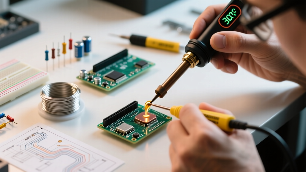
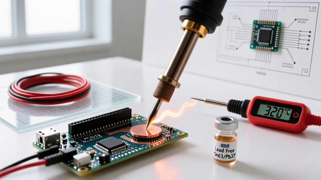
Many technicians set their Weller WE1010NA (approx. $110) or generic clone station to 350°C and assume the tip is exactly that temperature. In reality, the thermocouple inside the heating element measures the core temperature, not the working surface of the tip. When you touch a large ground plane, the tip surface temperature can plummet by 40°C or more, and the station's recovery time may be too slow to compensate, resulting in a cold joint even though the LCD still reads 350°C.
The Solution: Calibrate and Measure Recovery Time
Do not rely on static temperature readings. Invest in a tip thermometer, such as the Hakko FG-100B (approx. $180), which uses a K-type thermocouple sensor embedded in a thermal pad to measure the actual working surface temperature. More importantly, evaluate your station's thermal recovery. Cartridge-based systems like the JBC CD-2BQE (approx. $650) integrate the heater and sensor directly into the tip cartridge, allowing for a 2-second recovery time. If you are working with high-mass boards, upgrading to a cartridge system is a non-negotiable fix for thermal lag.
Mistake #2: Cranking the Heat to 'Fix' Poor Wetting
The Problem: Flux Burn-Off and Oxidation
When solder refuses to flow onto a large via or a multi-layer ground plane, the instinctive reaction is to crank the station dial up to 400°C (752°F). This is a catastrophic error. Standard rosin-based (RMA/RA) and no-clean fluxes activate between 150°C and 180°C. If the tip exceeds 350°C, the flux boils off and decomposes instantly upon contact, leaving behind a charred residue that actually inhibits wetting. Furthermore, temperatures above 380°C rapidly oxidize the iron plating on your tip, turning it black and non-receptive to solder.
The Solution: Preheating and Tip Geometry
If you are struggling with high thermal mass joints, the answer is not higher tip temperature; it is baseline preheating and increased surface area contact.
- Preheat the PCB: Use a bottom-side preheater like the Quick 853A (approx. $150) to bring the entire board up to 120°C - 150°C. This reduces the thermal delta your iron needs to overcome, allowing you to keep the iron at a safe 320°C.
- Change Tip Geometry: Switch from a fine conical tip to a wide chisel or a bevel (hoof) tip. A 3mm chisel tip transfers heat exponentially faster than a 1mm conical tip at the exact same temperature due to the increased contact area.
Mistake #3: Using Wet Sponges at High Temperatures
The Problem: Thermal Shock and Micro-Cracking
Wiping a 360°C lead-free soldering tip on a wet cellulose sponge causes an instantaneous, violent drop in surface temperature. This thermal shock induces micro-cracks in the iron's protective plating. Once the plating cracks, the molten solder dissolves the underlying copper core of the tip, leading to pitting, cratering, and permanent tip destruction within days.
The Solution: Dry Brass Wool
Discard the wet sponge. Use a dry brass wire sponge (often included with stations like the Hakko FX-951). Brass is softer than the iron plating but harder than the solder and oxides, allowing you to scrape away oxidation without dropping the tip's temperature or causing thermal shock. As highlighted in SparkFun's comprehensive soldering guide, maintaining tip tinning is crucial; always leave a blob of fresh solder on the tip before placing it back in the holder to act as a sacrificial oxidation barrier.
Mistake #4: Leaving the Iron at Max Temp During Idle Times
The Problem: Accelerated Tip Depletion
Leaving a soldering iron sitting at 350°C+ on a workbench while you debug code or inspect schematics is a surefire way to ruin the tip. Oxidation rates double for every 10°C increase above 300°C. An iron left idling at 380°C for 30 minutes will develop a thick, black oxide layer that refuses to wet, requiring aggressive cleaning that further shortens tip life.
The Solution: Auto-Sleep and Standby Modes
Ensure your station has an auto-sleep function. Modern stations detect when the handpiece is placed in the cradle and automatically drop the temperature to 150°C (or turn off completely). If your current station lacks this, manually dial it down to 200°C during idle periods. It takes a high-quality station less than 8 seconds to ramp back up to 340°C when you pick it up again.
Mistake #5: Ignoring the Component's Thermal Sensitivity
The Problem: Exceeding Maximum Thermal Ratings
Not all components can withstand standard lead-free soldering profiles. Certain RF modules, electrolytic capacitors, and plastic connectors have maximum casing temperatures of 220°C to 240°C. Applying a 360°C iron directly to the leads for more than 3 seconds can melt the internal die attach or warp the connector housing, leading to latent field failures.
The Solution: Heat Sinking and Low-Temp Alloys
For thermally fragile components, use aluminum heat-sink clips (like the E-Z-Hook micro-clips) on the leads between the joint and the component body to draw excess heat away. Alternatively, if the assembly allows, use a low-temperature alloy like Sn42Bi58 (melting at 138°C) for the final connections, keeping your iron at a gentle 230°C. The NASA Electronic Parts and Packaging (NEPP) soldering resources frequently document the use of thermal shunts and strict time-temperature limits for mission-critical, sensitive aerospace components.
Real-World Troubleshooting Matrix
Use this diagnostic matrix to quickly identify and correct temperature-related soldering defects on the bench.
| Visual Symptom | Likely Thermal Root Cause | Corrective Action |
|---|---|---|
| Cold Joint (Dull, grainy, bulbous) | Insufficient heat transfer; iron temp too low or tip too small for the pad's thermal mass. | Increase tip temp by 20°C, switch to a wider chisel tip, or apply bottom-side preheat. |
| Flux Charring (Black, crusty residue) | Tip temperature exceeds 380°C; flux is burning before it can clean the oxides. | Lower iron temp to 320°C-340°C. Apply fresh liquid flux externally before reheating. |
| Solder Balling / Non-Wetting | Tip is oxidized due to prolonged idling at high temps, or flux has boiled off. | Clean tip with brass wool, re-tin immediately. Lower idle temperature. |
| Pad Lifting / Delamination | Excessive dwell time (holding iron >5 seconds) or extreme temp (>400°C) on ENIG/HASL pads. | Reduce temp to 330°C. Preheat board. Improve technique to complete joint in <3 seconds. |
Final Thoughts on Thermal Precision
Mastering the soldering temperature for electronics is less about finding a single 'magic number' and more about understanding the dynamic relationship between your alloy, your tip geometry, and the thermal mass of the PCB. By abandoning the habit of cranking up the heat, utilizing preheaters for heavy ground planes, and respecting the chemical limits of your flux, you will drastically improve joint reliability and extend the lifespan of your expensive soldering equipment. Treat your thermal profile with the same rigor you apply to your schematic design, and your assemblies will consistently meet professional IPC standards.