
Masterclass: Soldering Copper Sheet for Custom RF Shields & Busbars
🎥 [00:00 - 01:15] Scene 1: The Thermal Mass Problem
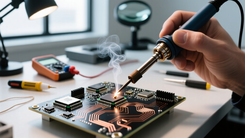
Camera Angle: Top-down macro shot. The lens focuses on a 0.030-inch thick copper sheet. A standard 40W soldering iron touches the surface; the solder wire merely skates and balls up, refusing to wet. The camera pans to a thermal imaging overlay showing the heat instantly dissipating across the metal.
When you transition from soldering delicate PCB traces to soldering copper sheet metal (typically 0.020" to 0.040" thick for RF shielding, custom enclosures, or high-current busbars), the rules of thermal dynamics change drastically. Copper boasts a thermal conductivity of approximately 401 W/m·K. It is a massive heat sink. If your iron lacks the thermal recovery rate to overcome this dissipation, you will inevitably create cold, grainy joints or warp the workpiece.
In this visual walkthrough, we break down the exact metallurgy, tooling, and 'sweat-soldering' techniques required to fabricate robust copper sheet assemblies, drawing on standards outlined by the IPC and high-reliability aerospace guidelines.
Gear Selection: Wattage & Tip Geometry
🎥 [01:16 - 03:30] Scene 2: The Tooling Bench
Camera Angle: Medium shot of the workbench. The host picks up a Weller WT1012N station, then swaps a standard conical tip for a massive, flat spade tip. Text overlays display the thermal mass specifications.
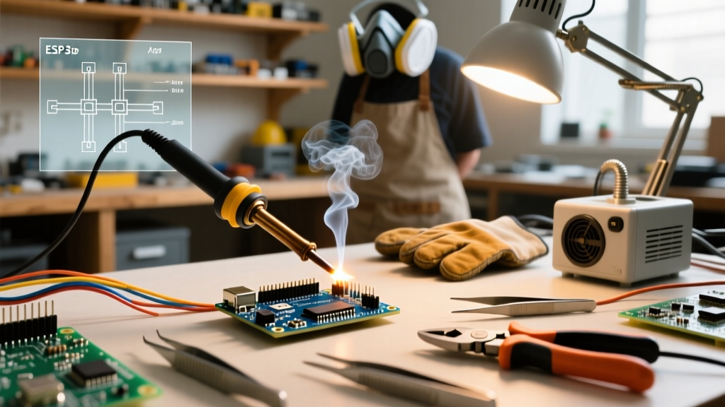
Forget the 40W to 60W irons used for standard 0805 SMD components. Soldering copper sheet demands high-wattage stations with heavy thermal reserves. As of 2026, the benchmark for serious DIY and prototyping is the Weller WT1012N (100W, ~$135) or the Hakko FX-952 (95W, ~$240). These stations utilize active sensor technology in the tip, detecting temperature drops and dumping maximum wattage into the heating element instantly.
Tip Geometry Matrix for Sheet Copper
Surface area contact is everything. Conical tips concentrate heat into a micro-point, which will scorch your flux and fail to heat the sheet. You need broad, flat geometries.
| Tip Geometry | Model Example (Hakko T18 / Weller ET) | Thermal Transfer Efficiency | Best Application |
|---|---|---|---|
| Wide Chisel / Spade (6mm+) | Hakko T18-D32 / Weller SMT8 | Excellent (Max Surface Contact) | Flat seams, RF shield walls |
| Heavy Bevel (45° Angle) | Hakko T18-C3 / Weller ETB | Good (Directional Heat) | Corner joints, internal baffles |
| Screwdriver / Flat Blade | Hakko T18-D16 / Weller ETA | Moderate | Tinning edges before assembly |
| Conical / Pencil | Hakko T18-I / Weller ETP | Poor (High Risk of Scorching) | Do NOT use on copper sheet |
Chemical Prep: Fluxing Heavy Copper
🎥 [03:31 - 05:00] Scene 3: Surface Oxidation & Flux Chemistry
Camera Angle: Extreme close-up. A piece of Scotch-Brite pad scrubs the copper, revealing bright pink metal. A brush applies a generous coat of amber liquid flux. The flux bubbles slightly as it meets the pre-heated metal.
Copper oxidizes rapidly when heated, forming cupric oxide, which solder absolutely will not wet. Mechanical prep is step one: use an abrasive pad (like Scotch-Brite) to remove heavy tarnish. Avoid steel wool, which embeds iron particles that will rust later. According to high-reliability guidelines from NASA's Workmanship Training, chemical activation must immediately follow mechanical cleaning.
Flux Selection for Copper Sheet
- Kester 186 (Mildly Activated Rosin - RMA): The gold standard for heavy copper. The rosin base protects the metal from re-oxidizing during the extended heat cycles required for sheet soldering. Requires isopropyl alcohol cleanup.
- Kester 245 (No-Clean): Excellent for RF shields where residue won't interfere with high-frequency signals. Leaves a hard, clear residue that is difficult to clean but electrically safe.
- Water-Soluble (Organic Acid): Use only if you plan to wash the assembly with hot distilled water immediately. Highly corrosive if left on copper; can cause galvanic corrosion over time.
The 'Sweat Soldering' Technique: Step-by-Step
🎥 [05:01 - 08:45] Scene 4: The Sweat Solder Sequence
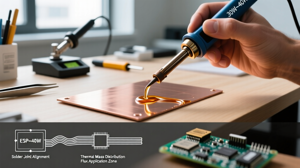
Camera Angle: Split screen. Left side shows the operator tinning two separate copper sheets. Right side shows the alignment and final reflow. Slow-motion replay highlights the solder wicking between the overlapping sheets via capillary action.
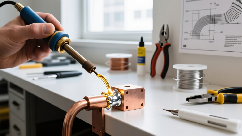
You cannot simply hold two thick copper sheets together and apply solder to the seam. The thermal mass will cool the iron tip below the solder's liquidus temperature before the base metal reaches it. The solution is sweat soldering (pre-tinning).
Phase 1: Pre-Tinning the Mating Surfaces
- Set Station to 360°C (680°F): If using Sn63/Pb37 eutectic solder (liquidus at 183°C), the high iron temperature compensates for the instant thermal drop when touching the copper.
- Flux the Overlap Zone: Apply Kester 186 to the inner mating surfaces of both copper sheets (e.g., a 0.25-inch overlap).
- Feed and Drag: Touch the wide spade tip to the copper, feed 0.062" diameter solder (like Kester 245 Core) directly into the leading edge of the tip, and drag slowly. The goal is a thin, mirror-finish layer of solder on the copper. Do not pool excessive solder.
Phase 2: Alignment and Reflow
- Fixture the Parts: Use high-temperature Kapton tape or heavy steel binder clips to hold the pre-tinned sheets together in the desired overlap.
- Apply External Flux: Paint a thin layer of flux over the exterior seam to aid capillary action.
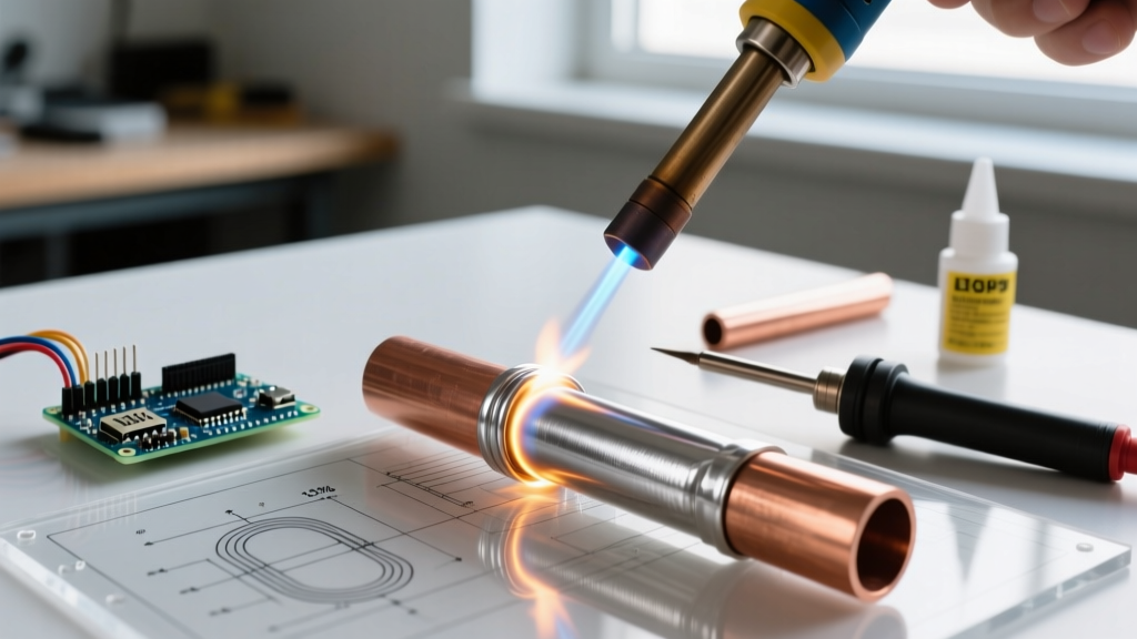
- The Reflow Pass: Press your pre-heated, fluxed spade tip directly onto the top sheet over the overlap zone. Hold for 3 to 5 seconds. Watch the edge of the seam: you will see the pre-applied solder melt and wick tightly into the joint. Drag the iron slowly down the seam, maintaining a steady 4-second dwell time per inch.
Thermal Management & Fixturing Hacks
🎥 [08:46 - 10:30] Scene 5: Warping & Heat Sinking
Camera Angle: Time-lapse of a thin 0.015" copper sheet warping like a potato chip under heat. The host then places the copper on a thick aluminum block, and the time-lapse shows perfectly flat soldering.
When soldering copper sheets thinner than 0.020", localized high heat will cause severe warping due to uneven thermal expansion. To combat this, fabricate or purchase a 6061 Aluminum Backing Plate.
Aluminum has high thermal conductivity but won't bond to standard rosin fluxes. By clamping your copper sheet flat against a 0.5-inch thick aluminum plate, the aluminum acts as a massive, uniform heat spreader. It pulls heat away from the immediate solder zone just enough to prevent warping, while still allowing the iron to maintain the 183°C+ threshold required for solder flow.
Troubleshooting Common Sheet Copper Failures
Even with the right wattage, heavy copper presents unique failure modes. Reference the Copper Development Association guidelines for metallurgical compatibility when diagnosing these issues:
- Grainy, Disturbed Joints: Cause: Movement during the plastic (pasty) phase of the solder cooling. Fix: Because copper sheet holds heat longer than PCB pads, the cool-down time is extended. Do not release the fixture clamps for at least 45 seconds after the iron is removed.
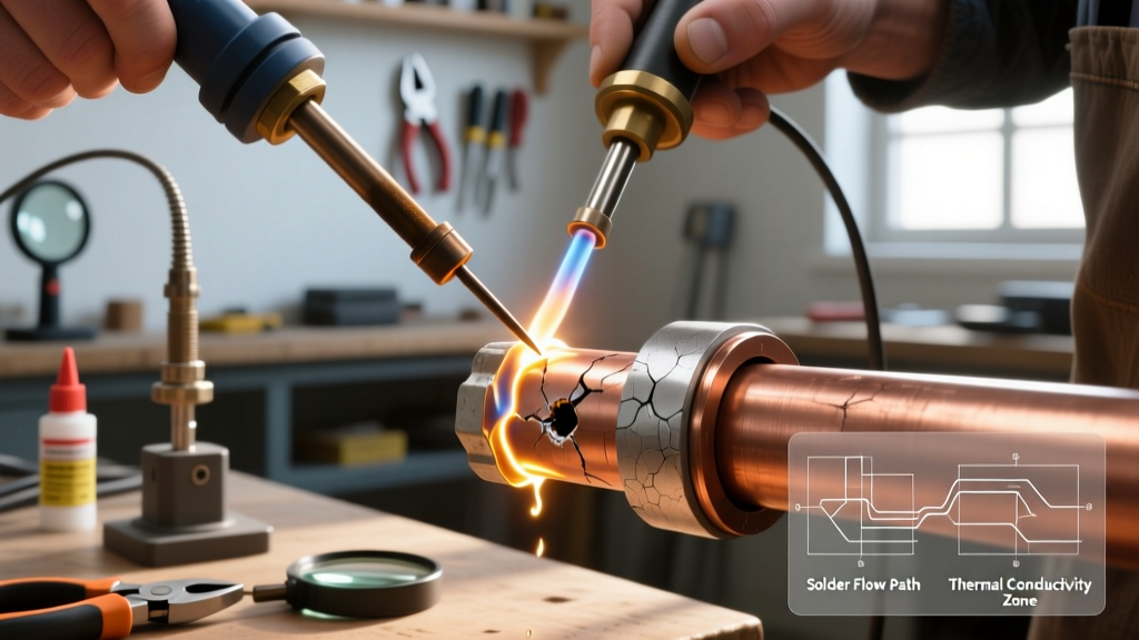
- Solder Balling / Dewetting: Cause: The flux has burned off before the copper reached thermal equilibrium, leaving a layer of cupric oxide. Fix: Lower the iron temp to 340°C, apply more liquid flux, and use a brass sponge to clean the tip before re-approaching the joint.
- Excessive Wicking (Solder migrating away from the seam): Cause: Solder flows toward the heat source. If your iron is on the top sheet, solder will wick up and over the edge. Fix: Apply heat directly over the center of the overlap, and use a physical heat barrier (like a damp cotton swab or Kapton tape) at the edges to define the solder boundary.
Final QA: Inspecting the RF Shield
🎥 [10:31 - 12:00] Outro: The 10x Loupe Inspection
Camera Angle: POV shot through a 10x jeweler's loupe. The camera scans the finished seam, showing a smooth, concave fillet with a bright, shiny finish. The host taps the shield with a torque screwdriver to verify mechanical rigidity.A properly soldered copper sheet joint should exhibit a smooth, concave fillet that blends seamlessly into the base metal. The surface should be bright and reflective (if using Sn63/Pb37). If you are building an RF shield for a 2.4GHz or 5GHz wireless module, this continuous solder seam provides the necessary Faraday cage effect, preventing EMI leakage that a simple mechanical press-fit enclosure would allow.
By respecting the thermal mass of copper, utilizing high-wattage active stations, and mastering the sweat-soldering sequence, you can fabricate custom enclosures and heavy-duty electronics assemblies that meet professional aerospace and telecom standards.