
The Anatomy of a Perfect Wire-to-Wire Splice
Whether you are repairing an automotive wiring harness, building a custom drone power distribution board, or extending sensor cables in an industrial environment, soldering wire to wire is a foundational skill. Yet, field failure analysis consistently shows that a vast majority of DIY and prototype wire splice failures are not caused by defective components, but by poor technique. A wire-to-wire joint must survive mechanical vibration, thermal expansion cycles, and environmental oxidation.
In this guide, we dissect the most critical mistakes makers and technicians make when joining wires, backed by industry standards and practical metallurgy. By understanding the thermal and mechanical physics at play, you can transition from making fragile, high-resistance joints to creating aerospace-grade connections.
Mistake 1: Relying on Solder for Mechanical Strength
The most pervasive myth in electronics is that solder acts as a structural adhesive. It does not. Solder is a soft alloy with low tensile strength designed exclusively for electrical continuity and thermal transfer. According to the IPC-A-620 Standards for cable and wire harness assemblies, a wire splice must have a mechanical connection capable of withstanding the physical stress of the application before the solder is even applied.
The Solution: The Western Union Splice
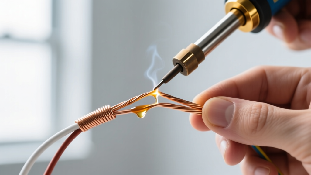
For solid and stranded core wires, the Western Union (or Lineman's) splice remains the gold standard. To execute it properly:
- Strip exactly 1.5 inches (38mm) of insulation from both wires.
- Cross the wires at a 90-degree angle, slightly offset from the center.
- Wrap each wire tightly around the opposing core a minimum of 4 to 5 times.
- Use flush cutters (like the Hakko CHP-170) to trim any protruding sharp ends flush against the core to prevent them from piercing your heat shrink later.
Expert Insight: If you are working with highly flexible silicone wire (e.g., 12 AWG battery leads), the Western Union splice can be too bulky. Instead, use a hook splice for quick connections, but always reinforce the joint with adhesive-lined dual-wall heat shrink to handle the tensile loads.
Mistake 2: Undersizing the Soldering Iron (Thermal Mass Failure)
When soldering wire to wire, the copper strands act as a massive heat sink. If you attempt to solder a 12 AWG power wire using a standard 40W hobby iron, the copper will pull heat away from the tip faster than the iron's heating element can replenish it. The result? You hold the iron in place for 15 seconds, the flux burns off, and you are left with a dull, grainy "cold solder" joint that will inevitably crack under vibration.
Wire Gauge to Iron Wattage Matrix
Matching your tool's thermal recovery rate to the wire's thermal mass is critical. Below is a reference chart for standard 63/37 Leaded Solder (Sn63Pb37):
| Wire Gauge (AWG) | Typical Application | Min. Iron Wattage | Target Tip Temp | Solder Diameter |
|---|---|---|---|---|
| 24 - 28 AWG | Signal / Data / I2C | 40W - 60W | 320°C (608°F) | 0.031" (0.8mm) |
| 18 - 22 AWG | Low Power / Servos | 60W - 70W | 340°C (644°F) | 0.040" (1.0mm) |
| 12 - 16 AWG | Power / Battery / ESC | 70W - 100W+ | 360°C (680°F) | 0.062" (1.5mm) |
| 8 - 10 AWG | High Current / Main | 100W+ (or Torch) | 380°C (716°F) | 0.080" (2.0mm) |
Tool Recommendation: For versatile wire splicing in 2026, the Pinecil V2 (approx. $26) offers 65W of rapid thermal recovery, while the Weller WE1010 ($110) provides a heavier thermal mass tip ideal for 14-18 AWG wires.
Mistake 3: The "Acid Core" Catastrophe
A trip to the plumbing aisle of a hardware store will yield solder that looks identical to electronics solder. However, plumbing solder utilizes an aggressive acid core (typically zinc chloride) designed to eat through the oxidation on copper pipes. If you use acid-core solder on electronics or automotive wiring, the residual acid will continue to corrode the copper strands long after the joint cools, resulting in green verdigris, high resistance, and eventual open-circuit failure.
The Solution: Rosin or No-Clean Flux
Always use solder formulated for electrical work. Kester 44 (Rosin Core) is the historical standard, providing excellent wetting but leaving a sticky residue that requires isopropyl alcohol cleanup. For modern wire splicing, Kester 245 No-Clean or MG Chemicals 8341 are superior choices. They leave a benign, non-conductive residue that does not attract moisture or cause dendritic growth.
Mistake 4: Insulation Burn-Back and Capillary Wicking
Solder behaves like water when exposed to heat and flux—it seeks the path of least resistance via capillary action. If your soldering iron touches the wire's insulation, or if you apply heat for too long, the molten solder will wick under the insulation jacket. This creates a rigid, brittle section of wire right at the flex point, guaranteeing a fatigue fracture over time.
The Solution: Thermal Stripping and Heat Sinking
- Precision Stripping: Use calibrated wire strippers (like the Klein Tools 11055) to avoid nicking the copper strands. Nicks create stress risers where the wire will snap when bent.
- The Heat Sink Trick: If you must solder near sensitive components or delicate insulation, clamp a pair of hemostats or an alligator clip onto the bare wire between the splice and the insulation. The metal clamp will absorb the excess thermal energy, preventing the heat from traveling down the wire and melting the jacket.
Mistake 5: Ignoring Metallurgy (Leaded vs. Lead-Free)
Many technicians apply the same temperature profiles to Lead-Free (SAC305) solder as they do to Leaded (Sn63Pb37) solder. SAC305 melts at 217°C–220°C, compared to the 183°C eutectic melt point of 63/37 leaded solder. Furthermore, lead-free solder has poor wetting characteristics and a narrower plastic phase.
When soldering wire to wire with SAC305, you must increase your iron temperature by 30°C to 40°C and utilize a highly active no-clean flux to compensate for the lack of lead. If you attempt to use lead-free solder at 320°C, you will experience severe tip oxidation and joint fracturing. As noted by the Adafruit Guide to Excellent Soldering, mastering the specific thermal profile of your chosen alloy is non-negotiable for structural integrity.
Mistake 6: Blowing on the Joint to Cool It
Impatience destroys splices. When you blow on a freshly soldered wire joint, you force the alloy through its plastic (semi-solid) state too rapidly. This disrupts the crystalline matrix formation, resulting in a disturbed joint. Visually, a disturbed joint looks grainy, frosty, and rough, mimicking a cold joint. Internally, it is riddled with micro-fractures that will fail under electrical load.
The Fix: Apply heat, feed the solder, remove the solder, remove the iron, and hold the wires perfectly still for 3 to 5 seconds. Allow the ambient air to cool the joint naturally. A perfect Sn63Pb37 joint will cool to a bright, mirror-like shine.
Mistake 7: Skipping Adhesive-Lined Heat Shrink
Standard single-wall polyolefin heat shrink provides basic electrical isolation, but it does not seal the joint against moisture, flux residue, or physical strain. In automotive or outdoor environments, moisture will wick into the stranded wire via capillary action, bypassing standard heat shrink entirely.
The Solution: Dual-Wall (Adhesive-Lined) Shrink Tubing
Always use 3:1 or 4:1 shrink ratio dual-wall tubing for wire-to-wire splices. When heated, the inner layer of thermoplastic adhesive melts and flows into the crevices of the stranded wire and the solder joint, while the outer polyolefin layer shrinks to create a rugged, waterproof mechanical strain relief. For a 14 AWG splice, a 3/16" (4.8mm) dual-wall tube will shrink down tightly, creating an IP67-rated environmental seal.
Summary: The 5-Step Perfect Splice Protocol
To guarantee success when soldering wire to wire, follow this exact sequence:
- Prep: Slide the adhesive-lined heat shrink onto one wire before starting. Strip wires using calibrated strippers.
- Mechanical Bond: Execute a tight Western Union splice with 4-5 wraps per side. Trim flush.
- Flux & Heat: Apply a small amount of external no-clean flux if using thick power wires. Touch the iron tip to the bottom of the splice, and feed solder into the top of the splice. Let capillary action draw the solder through.
- Cool: Remove heat and hold perfectly still for 4 seconds.
- Seal: Slide the dual-wall heat shrink over the joint, ensuring it overlaps the bare wire's insulation by at least 1/2 inch on both sides. Apply heat evenly until the adhesive bleeds slightly from the ends.
By respecting the mechanical and thermal requirements of the splice, your wire-to-wire connections will outlast the devices they are powering. For further reading on advanced workmanship requirements, consult the NASA Electronic Parts and Packaging (NEPP) Program documentation on soldering standards, which remains the benchmark for high-reliability aerospace wiring.