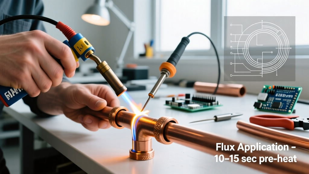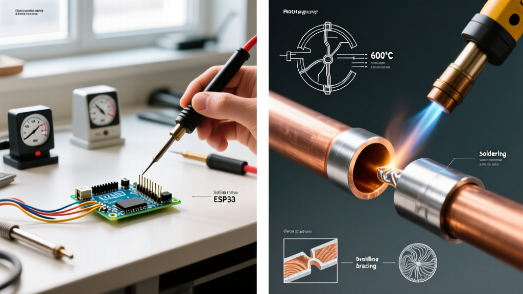

The Myth of the Universal 350°C Setting
In the realm of advanced electronics manufacturing and high-reliability rework, the concept of a single, universal ideal soldering temperature is a dangerous fallacy. Hobbyists and entry-level technicians are often taught to set their stations to 350°C and leave the dial alone. However, when working with modern high-density interconnect (HDI) boards, mixed-mass components, and advanced lead-free alloys, this brute-force approach leads to catastrophic failure modes: pad delamination, micro-cracking in multi-layer ceramic capacitors (MLCCs), and excessive intermetallic compound (IMC) overgrowth.
Finding the true ideal soldering temperature requires a dynamic approach. It is not about the temperature displayed on your station's LCD; it is about the thermal profile delivered to the specific solder joint within a strict time window. According to guidelines published by the IPC (Association Connecting Electronics Industries), the goal is to achieve a joint temperature of 40°C to 50°C above the alloy's liquidus point within 2 to 5 seconds. Exceeding this dwell time or relying on excessive tip heat to compensate for poor thermal transfer violates core workmanship standards.
The Physics of Thermal Transfer and the Delta-T Equation
To master advanced rework, you must understand the difference between tip temperature and joint temperature. When a 380°C chisel tip touches a 1206 capacitor connected to a 4-layer FR-4 board with internal ground planes, the tip temperature instantly drops. This is the Delta-T (ΔT) thermal drop.
If your soldering station lacks the wattage or thermal recovery speed to compensate for this ΔT, the technician will instinctively hold the iron on the pad longer. Prolonged dwell times (exceeding 5 seconds) cause the epoxy in the PCB substrate to reach its glass transition temperature (Tg), leading to subsurface delamination and via barrel cracking. Therefore, the ideal soldering temperature is actually a function of thermal mass and cartridge recovery rate, not just a static number.
Calculating Thermal Mass Variables
- Low Thermal Mass: 0402/0603 passives, fine-pitch QFPs on 2-layer boards. Requires lower tip temperatures (280°C - 310°C) to prevent tombstoning and pad lifting.
- Medium Thermal Mass: SOICs, standard QFNs, and electrolytic capacitors on 4-layer boards. Requires standard profiles (330°C - 350°C).
- High Thermal Mass: Connectors with heavy ground tabs, D2PAKs, and components on aluminum-core MCPCBs. Requires aggressive thermal delivery (360°C - 390°C) paired with high-wattage cartridges.
Alloy-Specific Temperature Profiles
The Surface Mount Technology Association (SMTA) frequently highlights the transition to varied lead-free and low-temperature alloys in modern assemblies. Your iron's tip temperature must be calibrated to the specific metallurgy of the solder paste or wire being used.
| Alloy Composition | Melting Point (Liquidus) | Ideal Tip Temperature Range | Max Dwell Time | Primary Use Case |
|---|---|---|---|---|
| Sn63/Pb37 (Leaded) | 183°C | 280°C - 310°C | 3.0 Seconds | Prototyping, aerospace, legacy repair |
| SAC305 (Sn96.5/Ag3.0/Cu0.5) | 217°C | 340°C - 360°C | 2.5 Seconds | Standard commercial lead-free RoHS |
| SAC405 (Sn95.5/Ag4.0/Cu0.5) | 217°C | 345°C - 365°C | 2.5 Seconds | High-reliability automotive/industrial |
| Sn42/Bi57/Ag1 (Low-Temp) | 138°C | 220°C - 240°C | 4.0 Seconds | Thermally sensitive components, flex PCBs |
| Sn99.3/Cu0.7 (SC) | 227°C | 350°C - 380°C | 2.0 Seconds | Wave soldering pots, heavy wire lugs |
Cartridge Geometry vs. Station Wattage
Setting the correct temperature on your dial is useless if the physical geometry of the tip cannot transfer the heat. In 2026, advanced stations like the JBC CD-2BE (retailing around $580) and the Hakko FX-970 utilize heater-in-cartridge technology, which drastically reduces the thermal path from the heating element to the joint.
However, geometry dictates thermal transfer efficiency. A conical tip (e.g., JBC C210-101) offers minimal surface area contact, resulting in a massive ΔT drop when touching a heavy ground plane. For high-mass joints, you must switch to a heavy chisel or bevel tip (e.g., JBC C245-945 or Hakko T18-D32) to maximize the contact patch. The ideal soldering temperature for a ground plane is best achieved by lowering the station temperature slightly (e.g., to 350°C) but using a massive chisel tip that stores and transfers high joules of thermal energy instantly, rather than cranking a fine-point tip to 420°C and cooking the component.
Intermetallic Compound (IMC) Growth and IPC Limits
One of the most insidious failure modes in advanced rework is IMC overgrowth. When molten solder reacts with the copper pad (or ENIG gold/nickel underlayer), it forms a metallurgical bond—typically the Cu6Sn5 eta phase. A thin, uniform IMC layer (1 to 3 microns) is necessary for a strong joint.
Expert Warning: If your tip temperature is too high, or your dwell time exceeds 4 seconds, the IMC layer grows excessively thick and transitions into the Cu3Sn phase. This creates a brittle, glass-like joint that will fracture under minor mechanical shock or thermal cycling. This is a primary focus in NASA's Electronic Parts and Packaging (NEPP) reliability studies for spaceflight hardware.
To prevent IMC overgrowth, advanced technicians use the "minimum necessary superheat" rule. If using SAC305 (liquidus 217°C), the joint only needs to reach roughly 250°C to flow and wet properly. The tip is set to 350°C solely to bridge the thermal gap between the iron and the joint in under 2 seconds.
Active Thermal Profiling Protocol
When reworking a $5,000 server motherboard or a densely packed RF transceiver board, do not guess the ideal soldering temperature. Profile it. Here is the standard operating procedure for mixed-mass thermal profiling:
- Attach K-Type Thermocouples: Use 30AWG K-type thermocouple wire secured with high-temperature Kapton tape. Attach one bead to the component body, one to the target pad, and one to an adjacent ground via.
- Establish Baseline Tg: Identify the PCB laminate's Tg (e.g., FR-408HR is typically 190°C). Your board's bulk temperature must never approach this threshold for more than a few seconds.
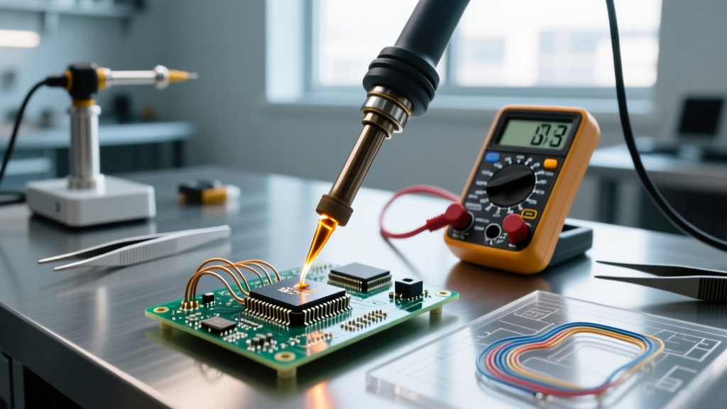
- Simulate the Rework: Apply flux and touch the iron to the test board (or a sacrificial identical board) while logging the temperature curve via a data logger (like the PACE SPT-200 or a standalone Fluke datalogger).
- Analyze the Delta-T: If the pad takes 6 seconds to reach 240°C, your tip is too small or your station wattage is too low. Do not increase the temperature dial; increase the tip mass.
- Verify with FLIR: For large BGA or QFN rework, supplement thermocouples with a thermal imaging camera (e.g., FLIR C5) to watch heat spread through internal vias and ensure adjacent components are not exceeding their thermal limits.
Edge Cases: ENIG Black Pad and MLCC Flex Cracking
Advanced boards frequently utilize Electroless Nickel Immersion Gold (ENIG) surface finishes. ENIG is notoriously susceptible to "black pad syndrome"—a brittle fracture caused by excessive corrosion of the nickel layer during soldering. Prolonged exposure to high-temperature soldering accelerates this galvanic reaction. Keeping your tip temperature strictly below 360°C for SAC alloys and removing the iron the instant the solder flashes to liquid is critical.
Similarly, MLCCs are highly vulnerable to thermal shock. Applying a 380°C iron to a cold 1210 MLCC pad causes a rapid localized expansion of the ceramic dielectric, resulting in invisible micro-cracks that will fail in the field. The ideal soldering temperature protocol for MLCCs involves pre-heating the board to 100°C using a bottom-side IR preheater, thereby reducing the ΔT shock when the top-side iron is applied.
Conclusion
Mastering the ideal soldering temperature is an exercise in thermal physics, not arbitrary dial-setting. By matching your cartridge geometry to the component's thermal mass, respecting the liquidus limits of your specific alloy, and adhering to strict IPC dwell-time guidelines, you eliminate the root causes of latent field failures. Invest in high-recovery heater-in-tip stations, profile your most complex boards with thermocouples, and let the data—not tradition—dictate your rework parameters.