
The Thermal Threshold: Defining the Divide
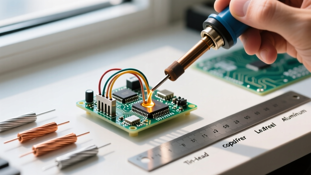
When working with metallic joints, understanding what is the difference between soldering and brazing is not just academic—it is the difference between a joint that lasts a lifetime and one that fails catastrophically under pressure. According to the American Welding Society (AWS) and metallurgical standards, the defining line between the two processes is a strict thermal threshold: 450°C (842°F).
If your filler metal melts below 450°C, you are soldering. If it melts above 450°C, you are brazing. In both processes, the base metals do not melt; only the filler alloy does, relying on capillary action to draw the molten metal into the joint. However, the thermal demands, flux chemistries, and structural outcomes are vastly different. Below, we break down the most common mistakes DIYers and junior technicians make when confusing these two techniques, and how to solve them.
Core Comparison Matrix: Soldering vs. Brazing
| Feature | Soldering | Brazing |
|---|---|---|
| Temperature Threshold | Below 450°C (842°F) | Above 450°C (842°F) |
| Typical Filler Metals | Sn63Pb37, SAC305, 95/5 Sn/Sb | BCuP-5 (Sil-Fos 15), BAg-24 (Easy-Flo) |
| Heat Source | Soldering iron, hot air, mild propane | Oxy-acetylene, MAP-Pro (TS8000 torch) |
| Joint Tensile Strength | Low to Moderate (up to ~15,000 psi) | High (often exceeds base metal strength) |
| Primary Applications | PCBs, electronics, low-pressure plumbing | HVAC refrigerant lines, structural steel, aerospace |
Mistake #1: Using Solder on High-Pressure or Vibrating Joints
The Error
A frequent and dangerous mistake in HVAC and automotive applications is attempting to use standard plumbing solder (like 50/50 or 95/5 Tin-Antimony) on refrigerant lines or high-vibration mechanical linkages. Solder lacks the shear strength and fatigue resistance to handle the thermal expansion cycles and high pressures (often exceeding 400 PSI in modern R-410A or R-32 systems) of these environments. Over time, the solder joint will develop micro-fractures and leak.
The Solution
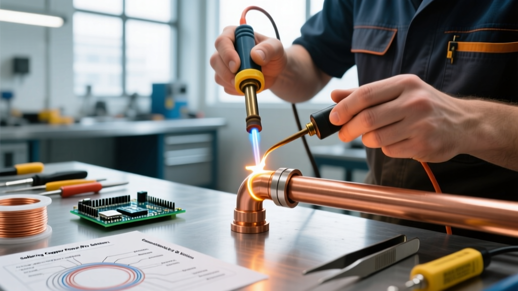
Switch to brazing using a silver-bearing copper-phosphorus alloy like BCuP-5 (commonly known as Sil-Fos 15 or Harris 0). This filler metal flows at approximately 1195°F to 1495°F (646°C to 813°C). To achieve this heat, abandon standard propane torches; use a Bernzomatic TS8000 with MAP-Pro gas, which generates a flame temperature of roughly 3,730°F, allowing you to quickly bring thick copper tubing up to brazing temperature without oxidizing the interior of the pipe. Always purge the line with dry nitrogen at 2-3 SCFH while brazing to prevent internal copper oxide scale, which can destroy HVAC compressor valves.
Mistake #2: Flux Incompatibility and Oxidation Failures
The Error
Flux is not a one-size-fits-all chemical. A major point of failure occurs when makers use rosin-based fluxes (designed for electronics soldering) for brazing, or attempt to braze steel using a flux meant for copper. Rossin flux activates around 150°C and carbonizes into a useless, sticky residue long before brazing temperatures are reached, resulting in a 'cold joint' where the filler metal balls up and refuses to wet the base metal.
The Solution
Match the flux chemistry to the thermal process and base metal:
- For Electronics Soldering (180°C - 350°C): Use RMA (Rosin Mildly Activated) flux or No-Clean flux. For lead-free SAC305 pastes, ensure the flux is specifically formulated for higher reflow profiles (up to 250°C).
- For Copper Plumbing Soldering (200°C - 250°C): Use a water-soluble zinc chloride-based paste like Harris Stay-Clean. It aggressively strips copper oxide at moderate heat.
- For Copper-to-Copper Brazing (600°C - 800°C): The phosphorus in BCuP alloys acts as a self-fluxing agent. No external flux is strictly required, though a white paste flux can extend the working time.
- For Steel or Stainless Steel Brazing (700°C+): You must use a potassium fluoborate or borax-based white flux (like Harris Stay-Silv White Flux) to dissolve the tough iron oxides that form at extreme heat. The Lucas-Milhaupt brazing fundamentals guide emphasizes that without proper borax-based flux, silver brazing alloys will simply not wet ferrous metals.
Mistake #3: Ignoring Capillary Joint Clearance
The Error
Both soldering and brazing rely on capillary action to pull molten metal into the joint gap. A common mistake is assuming that 'tighter is always better' or leaving massive gaps that the filler metal cannot bridge. If the gap is too tight, the flux gets trapped and prevents the alloy from entering. If the gap is too wide, capillary action fails, and the joint relies purely on the fillet (surface adhesion), which is structurally weak.
The Solution
Machine or ream your fittings to exact aerospace and plumbing tolerances. According to the Copper Development Association's Copper Tube Handbook, the ideal clearances are:
- Soldering Clearances: Maintain a diametrical gap between 0.002 and 0.004 inches (0.05 to 0.10 mm). This slightly wider gap accommodates the lower surface tension and higher viscosity of tin-based solders.
- Brazing Clearances: Maintain a tighter diametrical gap between 0.001 and 0.003 inches (0.025 to 0.075 mm). Because brazing alloys are highly fluid and operate at higher temperatures, the tighter gap maximizes capillary draw and joint tensile strength.
Mistake #4: Thermal Shock and PCB Pad Lifting
The Error
On the opposite end of the spectrum, some hobbyists attempt to use high-wattage, unregulated soldering tools (or worse, micro-torches) to solder heavy ground planes on printed circuit boards. Applying 800°F+ heat to a standard FR-4 fiberglass PCB will instantly exceed the glass transition temperature (Tg) of the board. This causes the copper pads to delaminate (lift) and destroys the plated through-holes (PTH), ruining the board.
The Solution
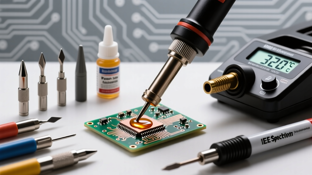
Never use brazing-level heat on electronics. Instead, use a digitally regulated soldering station like the Weller WE1010NA (70W) or Hakko FX-888D (65W). Set the iron to 320°C (608°F) for standard leaded wire work, or 350°C (662°F) for lead-free multilayer boards. If you are struggling to solder a massive ground plane due to heat sinking, do not turn the iron up to 450°C. Instead, use a wider chisel tip (e.g., a 3.2mm or 1/8" tip) to maximize thermal transfer surface area, and apply a small amount of liquid tack flux to accelerate wetting.
Diagnostic Checklist: Are You Soldering or Brazing?
Quick Diagnostic Test: Look at your filler metal packaging and your heat source.
- If your filler metal contains mostly Tin (Sn) or Lead (Pb) and melts with a standard 60W iron, you are soldering. Do not use this on load-bearing brackets or high-pressure gas lines.
- If your filler metal contains Silver (Ag), Copper (Cu), and Phosphorus (P), and requires a MAP-Pro or Oxy-Acetylene torch to melt, you are brazing. Do not use this on wires, microchips, or thin sheet metal that will warp.
Final Takeaway
Mastering what is the difference between soldering and brazing requires respecting the 450°C thermal boundary. By selecting the correct filler alloy, matching the flux chemistry to the base metal, and machining your joint clearances to exact decimal tolerances, you eliminate the vast majority of structural and electrical failures. Always prioritize the specific mechanical and thermal demands of your project over the convenience of the tools currently on your workbench.