
Introduction: The 'Silver Solder' Misconception
[Camera fades in on a macro shot of a gleaming, flawless solder joint on a 12 AWG copper wire. Studio lighting highlights the smooth, concave fillet.]
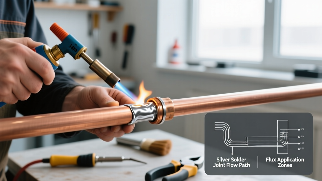
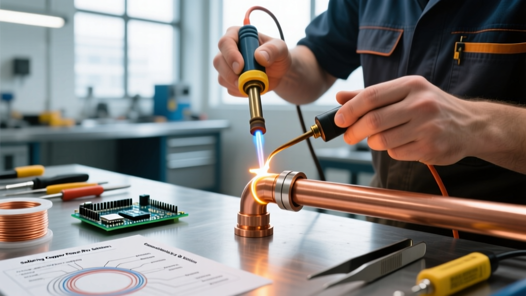
Welcome to the ElectricalFlux visual masterclass. Today, we are tackling a highly searched but frequently misunderstood technique: soldering copper with silver solder. Before we power on the Hakko FX-951 station, we must clear up a critical terminology trap. In the plumbing and HVAC world, 'silver solder' refers to high-temperature brazing alloys (like BAg-24) that melt at 1,300°F using an oxy-acetylene torch. But here in the electronics, microcontroller, and precision electrical domain, silver solder refers to Silver-bearing Lead-Free Alloys—specifically SAC (Tin-Silver-Copper) or Sn/Ag (Tin-Silver) formulations.
As of 2026, the shift toward high-reliability SAC305 and Sn96/Ag4 alloys in automotive, aerospace, and high-vibration wiring makes mastering this specific metallurgy essential. In this video-style visual guide, we will walk you through the exact camera angles, thermal profiles, and physical cues you need to achieve IPC-compliant joints with silver-bearing copper solder.
Scene 1: Gear & Metallurgy Breakdown
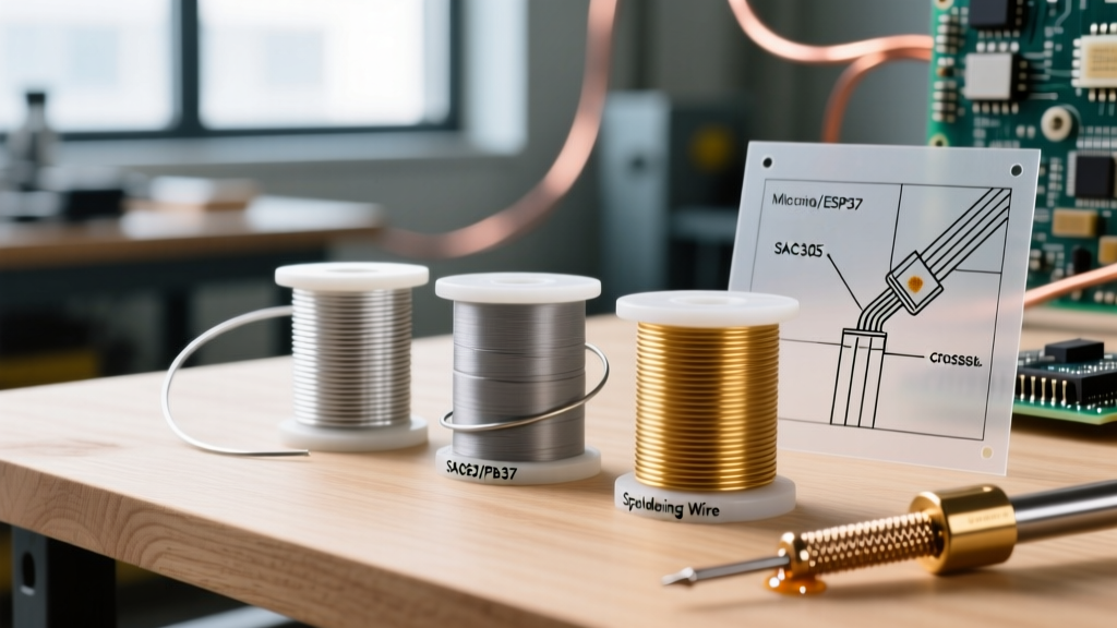
[Camera pans across a neatly organized workbench. Focus pulls to a spool of Kester wire and a digital soldering station.]
To successfully join copper with silver solder, you need to understand what is on your spool. Pure tin-silver (Sn96.5/Ag3.5) and tin-silver-copper (SAC305) are the industry standards.
- The Alloy: We are using Kester 24-6337-884 (SAC305) wire, 0.031' diameter. This alloy contains 96.5% Tin, 3.0% Silver, and 0.5% Copper. Expect to pay between $55 and $75 per 1lb spool in the current 2026 market.
- The Station: A Hakko FX-951 or Weller WE1010NA. Silver-bearing alloys have a higher liquidus temperature (217°C / 423°F) compared to traditional leaded solder (183°C). You need a station that can recover heat rapidly.
- The Tip: We recommend a chisel tip (like the Hakko T18-D24). Warning: Silver aggressively leaches iron from standard tip plating. Expect a 30% reduction in tip lifespan when running high-silver alloys daily.
🎥 On-Screen Graphic: Liquidus Temp: 217°C (423°F) | Iron Setpoint: 360°C (680°F) | Thermal Recovery: < 2 seconds
Scene 2: Surface Prep & Flux Application
[Close-up shot: Hands stripping a 14 AWG stranded copper wire. The copper is bright and free of oxidation.]
Silver-bearing solders possess higher surface tension than traditional Sn63/Pb37 leaded solders. They do not 'flow' as effortlessly; they require immaculate surface preparation to 'snap' into place.
- Mechanical Cleaning: Use a fiberglass scratch brush or 400-grit sandpaper to remove copper oxides. The wire must shine like a new penny.
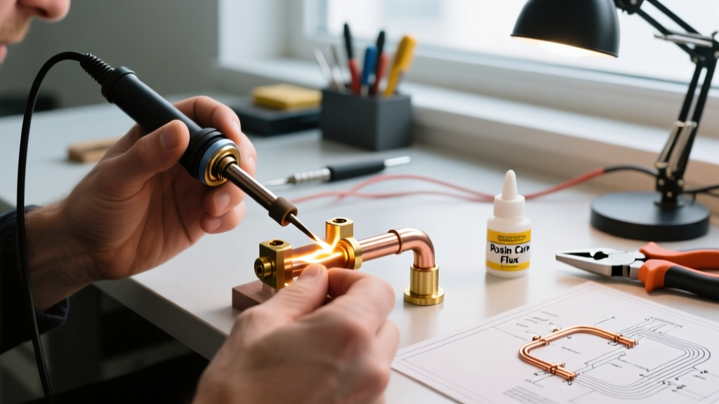
- Chemical Fluxing: We apply MG Chemicals 8341 No-Clean Flux or Kester 186 RMA (Rosin Mildly Activated). Dip the stripped copper end into the flux pot for 2 seconds.
- Pre-Tinning (Crucial Step): Apply the iron and feed a tiny amount of SAC305 to coat the strands. [Visual: The flux boils, turning amber, and the silver solder wicks between the strands via capillary action.]
According to the IPC J-STD-001 standard, proper wetting is impossible without the thermal and chemical assistance of flux, especially with the stubborn wetting characteristics of SAC alloys.
Scene 3: The Thermal Transfer & 'Snap' Wetting Action
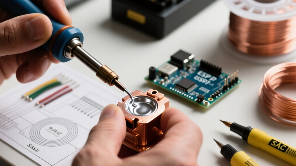
[Macro Lens: The camera is positioned at a 45-degree angle, capturing the exact moment the soldering iron meets the copper pad and wire.]
This is where most technicians fail when transitioning to silver solder. They expect the liquid puddle behavior of leaded solder. Silver solder behaves differently.
The 3-Second Rule
- Seconds 0-1 (Heat Transfer): Place the 360°C chisel tip so it bridges the copper pad and the pre-tinned wire. Do NOT apply solder wire yet. Let the thermal mass equalize.
- Seconds 1-2 (Flux Activation): You will see the flux bubble and turn slightly transparent. This indicates the copper has reached the ~220°C activation threshold.
- Seconds 2-3 (The Feed & Snap): Feed the SAC305 wire into the joint, not the iron tip. [Visual: The solder does not melt into a wide puddle; it suddenly 'snaps' or 'tacks' onto the copper, forming a tight, shiny meniscus.]
- Seconds 3-4 (Freeze): Remove the solder wire, then remove the iron. Hold the wire perfectly still for 3 seconds.
⚠️ Expert Note: Silver-bearing alloys have a distinct 'plastic' or 'mushy' state just above their solidus temperature. If the copper wire moves during this 3-second cooling window, the joint will fracture internally, resulting in a 'grainy' or disturbed joint—a critical failure mode detailed by the NASA Electronic Parts and Packaging (NEPP) program.
Scene 4: Troubleshooting the 'Grainy' & 'Dull' Joint
[Split-screen comparison: Left side shows a perfect, shiny SAC305 joint. Right side shows a dull, gray, textured joint.]
When soldering copper with silver solder, visual inspection is your primary quality control metric. Here is how to read the visual feedback:
- The Grainy/Dull Joint: Caused by micro-movements during the plastic cooling phase, or by using an iron temperature that is too low (below 330°C), causing the silver to precipitate out of the tin matrix unevenly.
- The Bulbous/Non-Wetting Joint: The solder forms a ball on the wire rather than a concave fillet. This means the copper was oxidized, or the flux was burned off before the copper reached 217°C. Fix: Clean, re-flux, and increase dwell time by 1 second.
- Pitted Surface: Caused by excessive flux boiling trapped under a solder layer that skinned over too quickly. Lower your iron temp by 10°C to allow flux vapors to escape.
Scene 5: Alloy Comparison Matrix
[On-Screen Graphic: A sleek comparison table fades in over a blurred background of the workbench.]
To ensure you are selecting the correct 'silver solder' for your specific copper application, reference this matrix:
| Alloy Type | Composition | Melt Temp (Liquidus) | Primary Use Case | Visual Characteristic |
|---|---|---|---|---|
| SAC305 | 96.5% Sn, 3.0% Ag, 0.5% Cu | 217°C (423°F) | PCB, Microcontrollers, Wiring | Shiny, slightly stiffer meniscus |
| Sn96/Ag4 | 96% Sn, 4% Ag | 221°C (430°F) | High-vibration, Aerospace wire | Very bright, excellent shear strength |
| Sn63/Pb37 | 63% Sn, 37% Pb (Reference) | 183°C (361°F) | Legacy/Hobby electronics | Highly fluid, glossy puddle |
| BAg-24 (HVAC) | 50% Ag, 34% Cu, 16% Zn | 704°C (1300°F) | Refrigeration lines, Plumbing | Requires torch; brazing, not soldering |
For deeper metallurgical insights into why the addition of copper to the tin-silver matrix (SAC) reduces the melting point and improves thermal fatigue resistance, review the Indium Corporation's technical breakdown of SAC alloys.
Scene 6: Post-Solder Cleaning & Final Inspection
[Camera: Top-down view. A technician uses a cotton swab and 99% Isopropyl Alcohol to clean the joint.]
Even if you use a 'No-Clean' flux, the residue from silver-bearing solder processes can sometimes trap moisture if the thermal profile was too aggressive. For high-reliability electrical copper connections:
- Allow the joint to cool to room temperature (approx. 45 seconds for 12 AWG wire).
- Scrub the joint with a lint-free swab saturated in 99% IPA.
- Inspect under a 10x loupe or digital microscope. You are looking for a smooth, continuous fillet that wets the copper wire and the terminal pad at an angle of less than 45 degrees.
[Camera pulls back to a wide shot of the completed, gleaming copper harness. Fade to black.]
Mastering soldering copper with silver solder requires respecting the higher thermal thresholds and unique wetting physics of SAC and Sn/Ag alloys. By controlling your dwell time, managing your flux chemistry, and holding the joint perfectly still during the plastic cooling phase, you will produce electrical connections that withstand extreme vibration and thermal cycling for decades.