
Welcome to the Visual Studio: Mastering Heat Transfer
Grab your safety glasses and pull up a chair. Welcome to the ElectricalFlux visual studio. Today, we are moving beyond basic text tutorials and diving into a video-style visual guide focused entirely on the most critical variable in electronics assembly: soldering temperature. Whether you are dragging solder across a 0.4mm pitch QFP chip or sweating thick 10 AWG silicone wires, guessing your dial settings will lead to catastrophic pad delamination or brittle cold joints.
In this guide, we will use mental 'macro-lens' descriptions, thermal camera breakdowns, and side-by-side equipment comparisons to show you exactly what happens at the tip-to-pad interface. By the end of this visual walkthrough, you will know precisely how to calibrate your station for the modern 2026 component landscape.
Scene 1: The Thermal Camera Reveal – Why Guessing Fails
[Visual Cue: The screen fades in on a FLIR thermal imaging view of a populated PCB. The iron tip touches a ground-plane via.]
Watch the heat bloom on the thermal monitor. When a 350°C iron tip touches a standard signal trace, the target pad reaches the solder's liquidus phase in roughly 1.5 seconds. But look at the adjacent ground-plane via. The massive copper mass acts as a thermal heat sink, wicking the heat away instantly. The pad temperature barely crosses 180°C.
This is where beginners fail. They see the solder refuse to flow on the ground pin, so they hold the iron there for 10 seconds. [Camera zooms in on the FR4 fiberglass substrate]. The prolonged heat exposure causes the resin to exceed its glass transition temperature (Tg), leading to microscopic delamination and barrel cracking in the via. The optimal soldering temperature isn't a single static number; it is a dynamic calculation based on the thermal mass of the specific joint you are attacking.
Director's Note: According to workmanship standards published by NASA's Electronic Parts and Packaging (NEPP) Program, excessive dwell time (typically over 3 to 5 seconds per joint) is a primary cause of latent thermal damage to multilayer PCBs, even if the joint looks visually acceptable on the surface.
Scene 2: Equipment Calibration – Pinecil V2 vs. Hakko FX-888D
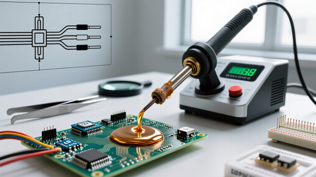
[Visual Cue: Split-screen comparison. Left side: The ultra-portable Pinecil V2. Right side: The benchtop Hakko FX-888D.]
Let us look at the hardware driving our heat. In the current 2026 market, the Pinecil V2 (powered by a RISC-V BL706 chip) remains the undisputed budget king at roughly $28. Its 65W PD (Power Delivery) capability allows it to recover from thermal drops in milliseconds. On the right, the legendary Hakko FX-888D benchtop station, now hovering around $125, relies on a 70W ceramic heating element and a heavier, high-thermal-mass T18 tip series.
The Calibration Reality Check
Do not trust the digital readout blindly. A Hakko set to 350°C at the dial might only deliver 335°C to the tip due to ambient heat loss and tip oxidation. Here is how we calibrate in the studio:
- Step 1: Apply a small dab of SAC305 (lead-free) solder to the tip. If it balls up and refuses to wet the iron, your actual tip temperature is below 217°C, regardless of what the screen says.
- Step 2: Use a tip thermometer (like the Hakko FG-100B, approx. $220) to measure the true surface temperature. Offset your station's calibration menu until the physical tip reads exactly 350°C.
- Step 3: For heavy ground planes, swap to a chisel tip (e.g., T18-D24). The increased surface area transfers thermal energy far more efficiently than simply turning up the dial to 400°C, which will rapidly oxidize and destroy your tip.
Scene 3: The Master Soldering Temperature Matrix
[Visual Cue: A sleek, high-contrast data matrix appears on screen, detailing exact parameters for common alloys.]
Memorize this matrix. These parameters align with IPC-A-610 acceptability requirements for electronic assemblies, ensuring proper wetting and concave fillet formation.
| Alloy Type | Composition | Melting Point (Liquidus) | Optimal Iron Temp | Max Dwell Time | Visual Flow Cue |
|---|---|---|---|---|---|
| Eutectic (Leaded) | Sn63 / Pb37 | 183°C (361°F) | 315°C - 330°C | 2.0 - 3.0 sec | Instant mirror finish, rapid capillary wicking |
| Lead-Free (Standard) | SAC305 (Sn96.5/Ag3/Cu0.5) | 217°C (423°F) | 345°C - 360°C | 2.5 - 4.0 sec | Slightly duller finish, requires active flux core |
| Low-Temp (Rework) | Sn42 / Bi58 | 138°C (280°F) | 220°C - 250°C | 1.5 - 2.0 sec | Very fast melt, brittle joint, strictly for rework |
| High-Temp (Hi-Rel) | Sn10 / Pb90 | 268°C (514°F) | 380°C - 400°C | 3.0 - 5.0 sec | Sluggish flow, requires aggressive RA flux |
Scene 4: Macro Shots – Reading the Solder Flow
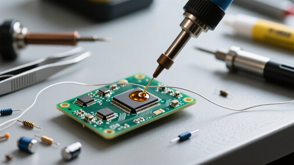
[Visual Cue: Camera switches to a 10x macro lens. We are watching a 0805 SMD resistor being soldered.]
Watch the flux activation. As the 350°C tip touches the component pad, the rosin-based flux core melts at roughly 150°C, well before the solder alloy. You will see a microscopic wave of liquid flux wash over the copper, stripping away nanometers of oxidation. This is the 'cleaning phase'.
Now, feed the SAC305 wire into the joint, not the iron tip. [Slow-motion playback]. The solder hits the fluxed pad and instantly flashes into a liquid state, pulling itself up the component's nickel-plated termination via capillary action. The resulting fillet forms a smooth, concave 'heel' and 'toe'. If the solder forms a convex dome or balls up on the component lead without wetting the PCB pad, your soldering temperature was too low, or your thermal transfer was interrupted by a cold tip.
For authoritative guidance on identifying these microscopic wetting angles and fillet shapes, the Hakko USA Soldering 101 knowledge base provides excellent visual references for distinguishing between acceptable concave fillets and rejectable disturbed joints.
Scene 5: Thermal Failure Autopsy – What Went Wrong?
[Visual Cue: The lighting shifts to a harsh, clinical white. We are examining three failed PCBs under a digital microscope.]
Failure A: The 'Grape' Cold Joint
The Visual: The solder looks like a dull, lumpy grape sitting on top of the pad. The outline of the wire or lead is still distinctly visible inside the solder mass. The Cause: The soldering temperature at the workpiece never reached the liquidus point. The iron melted the solder, but the cold pad caused the alloy to freeze instantly upon contact, preventing metallurgical intermetallic compound (IMC) formation. The Fix: Increase iron temp by 15°C, use a wider chisel tip, or pre-heat the PCB to 100°C using a silicone heating mat.
Failure B: The Cratered Pad (Lifted Land)
The Visual: The copper pad has peeled away from the fiberglass substrate, taking the trace with it. The solder is bonded to a floating island of copper. The Cause: Excessive temperature (e.g., 420°C+) combined with prolonged dwell time (8+ seconds), or applying mechanical downward pressure with the iron tip while the FR4 resin was softened. The Fix: Never exceed 380°C for standard FR4 boards. Use thermal relief spokes on ground-plane vias in your PCB CAD software to limit heat dissipation, allowing faster soldering at lower temperatures.
Failure C: Tombstoning (SMD Components)
The Visual: A 0402 capacitor stands straight up on one end, resembling a tombstone. The Cause: Asymmetric heating. One pad reached the optimal soldering temperature and reflowed before the other. The surface tension of the molten solder on the hot side pulled the component upright. The Fix: Apply the iron tip so it bridges both pads equally, or use a hot air rework station set to 280°C with a 10mm nozzle to heat the entire component footprint simultaneously.
Scene 6: Quick-Cut FAQ Wrap-Up
[Visual Cue: Fast-paced text-on-screen Q&A format with rapid host voiceover.]
Q: Should I turn my iron down to 250°C to 'save' the tip when not in use?
A: No. Turning a station off and on causes massive thermal cycling stress. Instead, use a station with an auto-sleep feature (like the Weller WE1010NA or Pinecil) that drops the tip to 150°C when the handle is holstered, then flashes back to 350°C in 4 seconds when picked up.
Q: Does lead-free solder require a higher temperature than leaded?
A: Yes. Because SAC305 melts at 217°C (compared to 183°C for Sn63/Pb37), you must run your iron roughly 30°C to 40°C hotter to maintain the same thermal delta and ensure proper wetting.
Q: Why is my solder sticking to the iron tip and not the pad?
A: Your tip is oxidized, acting as a thermal insulator. Do not scrape it with a steel file. Drop the temperature to 250°C, aggressively scrub the tip on a damp brass sponge while feeding a massive amount of high-flux cored solder to re-tin and protect the iron plating.
Final Cut: Respect the Thermal Delta
[Visual Cue: Camera pulls back to a wide shot of the workbench. The host powers down the station.]
Mastering your soldering temperature is not about finding one magic number; it is about understanding the thermal delta between your heating element, your tip geometry, and the copper mass of your workpiece. By matching your alloy to the correct temperature matrix, utilizing the right tip mass, and respecting the 3-second dwell time rule, you will produce IPC-compliant, mechanically robust joints every single time. Keep your tips tinned, trust your thermal data, and we will see you in the next studio session.