
The Metallurgy of Reliability: Beyond the Spool
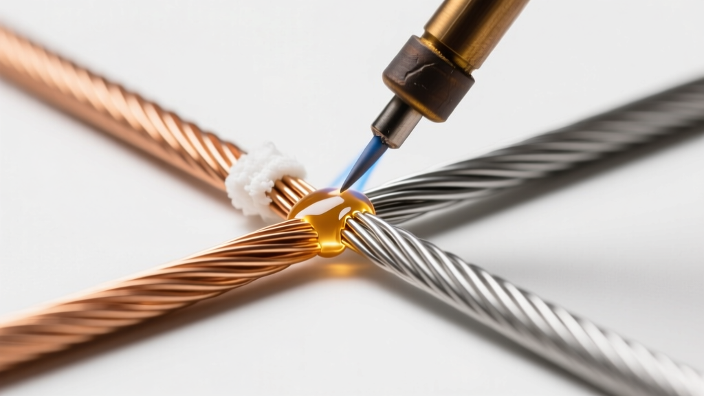
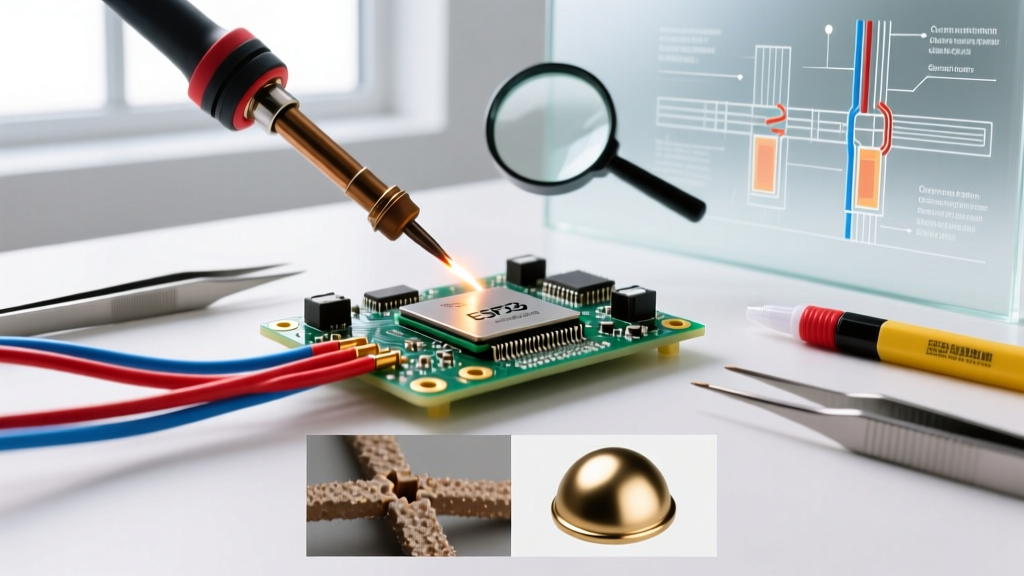
When evaluating the material of soldering wire, amateur hobbyists often default to whatever is cheapest or most accessible. Professional electronics assembly engineers, however, understand that the specific alloy composition and flux chemistry dictate the long-term reliability, thermal fatigue resistance, and electrical conductivity of the final joint. In modern PCB manufacturing and high-reliability rework, selecting the correct material of soldering wire is a critical engineering decision that impacts everything from wetting behavior to the formation of intermetallic compounds (IMCs) at the pad interface.
As of 2026, the transition to lead-free manufacturing is largely complete in commercial sectors, yet high-reliability aerospace, medical, and automotive applications still leverage specific leaded or specialized alloys to mitigate failure modes like tin whiskers and thermal shock cracking. This guide breaks down the professional considerations for selecting the optimal solder wire for your specific application.
Core Alloy Comparison Matrix
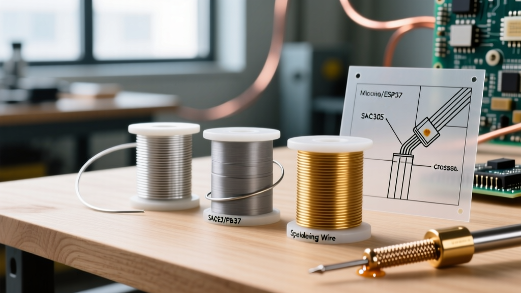
The base metal alloy determines the melting profile, mechanical strength, and wetting characteristics. Below is a professional comparison of the most prevalent alloys used in hand soldering and selective soldering processes.
| Alloy Designation | Composition | Melting Profile (°C) | Tensile Strength (MPa) | 2026 Avg Cost (500g Spool) | Primary Use Case |
|---|---|---|---|---|---|
| Sn63/Pb37 | 63% Tin, 37% Lead | 183°C (Eutectic) | ~52 | $35 - $45 | Aerospace, medical, rapid prototyping |
| SAC305 | 96.5% Sn, 3.0% Ag, 0.5% Cu | 217°C - 220°C | ~58 | $85 - $115 | Commercial lead-free, high-vibration |
| Sn99.3/Cu0.7 | 99.3% Tin, 0.7% Copper | 227°C (Eutectic) | ~48 | $40 - $55 | Cost-sensitive lead-free, wave soldering |
| Sn42/Bi57 | 42% Tin, 57% Bismuth, 1% Ag | 138°C - 140°C | ~65 (Brittle) | $120 - $150 | Heat-sensitive components, step-soldering |
According to the IPC J-STD-001 standards for soldered electrical and electronic assemblies, the choice of alloy must align with the operational environment of the end product. For instance, while SAC305 offers superior tensile strength, its higher liquidus temperature (220°C) requires hotter iron tips (typically 350°C - 380°C), which accelerates tip oxidation and increases the risk of thermal damage to sensitive SMD components.
Flux Chemistry: The Hidden Half of the Material
The metallic alloy is only half the story. The flux core inside the wire is what enables the metallurgical bond by reducing metal oxides and promoting wetting. Professional buyers specify flux according to IPC J-STD-004 classifications, focusing on activity level and cleanability.
No-Clean (ROL0 / ROL1)
No-clean fluxes, such as the widely used Kester 245 or Senju ECO SOLDER, leave behind a clear, hard, non-conductive residue. ROL0 (Rosin, Low activity, zero halides) is the industry standard for consumer electronics where post-solder cleaning is economically unviable. Pro Tip: If you are performing bare-board testing (ICT) with pogo pins, heavy no-clean residue can cause false failures. In these cases, specify a low-residue ROL1 variant or plan for a localized cleaning step.
Water-Soluble (ORH0 / ORH1)
Organic acid (OA) fluxes are highly active and designed to be cleaned with DI water immediately after soldering. They are mandatory for high-power RF boards or medical implants where any residual ionic contamination could lead to electrochemical migration (dendrite growth) and catastrophic short circuits. Never leave water-soluble flux residues on a PCB overnight; the corrosive acids will begin eating the copper traces within hours.
Rosin Activated (RA)
RA fluxes contain halide activators that aggressively strip heavy oxidation. While excellent for soldering to poorly finished or oxidized legacy boards, they require thorough cleaning with saponifiers or specialized solvents to prevent long-term corrosion.
Application-Specific Pro Selections
Selecting the right material of soldering wire requires matching the physical geometry of the joint and the thermal mass of the components.
- Fine-Pitch SMD (0402 / 0201 Passives, 0.4mm pitch QFNs): Use Sn63/Pb37 or a low-temperature Sn42/Bi57 alloy in a micro-diameter wire (0.010" or 0.25mm). The lower melting point prevents pad lifting on delicate HDI substrates, and the eutectic transition ensures the joint snaps solid instantly, preventing cold joints from micro-movements during the phase change.
- High-Vibration and Automotive ECUs: SAC305 is the undisputed champion here. The 3% silver content forms Ag3Sn intermetallic plates within the tin matrix, drastically improving resistance to mechanical shock and thermal cycling. Use a 0.031" (0.8mm) wire with a 2% to 3% flux core to ensure adequate wetting on thick copper planes.
- Heavy Copper Planes and Ground Lugs: When soldering to 2oz or 4oz copper pours, the thermal dissipation is massive. Professionals use Sn99.3/Cu0.7 with a high-activity ROL1 no-clean flux and a large chisel tip (e.g., Weller RT8 or Hakku T12-D52) driven at 400°C. The copper in the alloy prevents the solder from aggressively leaching the copper from the PCB pad during the extended dwell time required to heat the massive thermal mass.
Edge Cases and Failure Modes
Expert Warning on Bismuth Alloys: Never mix Sn42/Bi57 (Bismuth-based) solder with lead-containing finishes or HASL (Hot Air Solder Leveling) boards. The introduction of even trace amounts of lead into a bismuth alloy creates a ternary eutectic that melts at a mere 96°C. This will cause the joint to literally melt apart during standard operational heating or subsequent rework steps.
Tin Whisker Mitigation
Pure tin and high-tin lead-free alloys (like SAC305 and SnCu) are susceptible to tin whisker growth—microscopic crystalline structures that can bridge adjacent pads and cause short circuits. According to research published by the Indium Corporation, adding a minimum of 2% to 3% lead to the alloy, or utilizing specialized matte-tin suppressive conformal coatings, remains the most reliable mitigation strategy for mission-critical aerospace and defense applications where zero-failure tolerance is mandated.
Copper Leaching in Selective Soldering
When using high-tin lead-free wires for extended hand-soldering sessions on ENIG (Electroless Nickel Immersion Gold) or bare OSP (Organic Solderability Preservative) pads, the tin in the solder will dissolve the copper from the pad. If your dwell time exceeds 4 seconds per joint, you risk creating a brittle, copper-depleted intermetallic layer that will fail under mechanical stress. Always use a temperature-controlled station with high thermal recovery rates to minimize the time the iron spends on the pad.
Frequently Asked Questions (FAQ)
Does the diameter of the soldering wire affect the joint quality?
Absolutely. Using a wire that is too thick (e.g., 0.062") for a fine-pitch SMD pad forces the operator to feed the wire slowly, leading to excessive iron dwell time and thermal damage. Conversely, using micro-wire (0.015") on a large ground plane will require feeding inches of wire, cooling the joint and causing a massive, uninspectable blob of cold solder. Match the wire volume to the joint volume: 0.020" for standard 0603/0805 SMD, and 0.031" to 0.040" for through-hole and heavy terminals.
Why is my SAC305 solder wire leaving a dull, grainy finish?
A dull or grainy finish in lead-free SAC alloys is often a sign of a disturbed joint during the plastic (mushy) phase between the solidus (217°C) and liquidus (220°C) temperatures, or it indicates excessive flux burnout. Ensure your soldering iron tip is clean, properly tinned, and that you are not moving the component before the solder has fully crystallized.
Can I use plumbing solder for electronics?
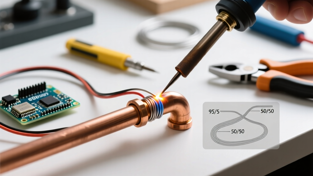
Never. Plumbing solder (often 95/5 Sn/Sb or 50/50 Sn/Pb) uses highly corrosive acid fluxes (zinc chloride or ammonium chloride) designed to clean copper pipes. If used on a PCB, the acid flux will rapidly corrode the delicate copper traces, cause immediate short circuits, and destroy the board. Always use electronic-grade rosin or synthetic no-clean fluxes.
Final Professional Recommendations
Mastering the material of soldering wire is about understanding the metallurgical and chemical interactions at the joint interface. For general commercial rework and prototyping in 2026, a high-quality SAC305 wire with a 2.2% ROL0 no-clean flux core remains the most versatile choice. However, for high-reliability, high-vibration, or extreme-temperature environments, engineering the exact alloy and flux combination to match the PCB surface finish and component thermal mass is non-negotiable. Invest in premium, tightly specified wire from manufacturers like Kester, Indium, or Senju, and maintain strict climate-controlled storage (below 25°C and 50% RH) to prevent the flux core from degrading or the wire surface from oxidizing before it ever touches your iron.