
Understanding Your Desoldering Tools: Manual vs. Electric
When learning how to use a desoldering pump, the first step is understanding the mechanics of your tool. Desoldering pumps, commonly known as solder suckers, rely on a sudden vacuum release to pull molten solder away from printed circuit board (PCB) pads and through-holes. While electric desoldering stations like the Hakko FR-301 are excellent for high-volume manufacturing, manual pumps remain the gold standard for precision DIY repair and fieldwork due to their tactile feedback and zero risk of continuous thermal runaway.
Not all manual pumps are created equal. The Engineer SS-02 Desoldering Pump is widely regarded by professionals for its slim 2.2mm PTFE (Teflon) tip, which allows for tight clearance around dense surface-mount pads and prevents solder adhesion to the nozzle. Conversely, heavy-duty pumps like the Edsyn SOLDAPULLT DS017 feature aggressive spring tension for maximum vacuum, but their bulkier nozzles can accidentally bridge adjacent pins on fine-pitch ICs. Choosing the right tool dictates your success rate in avoiding collateral damage to the PCB.
Preparation: The Secret to Lifted-Pad-Free Removal
The most catastrophic failure in PCB repair is lifting a copper pad from the fiberglass substrate. This occurs when the adhesive bonding the copper to the FR4 material degrades due to prolonged heat exposure. To prevent this, preparation is non-negotiable.
The Fresh Solder Technique
Counterintuitively, the best way to remove old, oxidized solder is to add fresh solder. If you are working on a legacy board with lead-free solder (which requires high temperatures around 360°C to melt), apply a generous amount of 63/37 tin/lead eutectic solder to the joint. This lowers the overall melting point of the joint to roughly 183°C, drastically reducing the time your soldering iron needs to dwell on the pad.
Flux is Your Thermal Bridge
Never attempt to desolder a dry joint. Apply a high-quality no-clean or rosin-based flux gel, such as Amtech NC-559-V2-TF or Chip Quik SMD291AX. Flux removes oxidation, improves thermal transfer from your iron tip to the joint, and lowers the surface tension of the molten solder, allowing the vacuum pump to extract it cleanly.
Step-by-Step Tutorial: How to Use a Desoldering Pump Effectively
Follow this precise sequence to ensure complete solder extraction without damaging sensitive components or PCB traces.
Step 1: Prime the Pump and Apply Heat
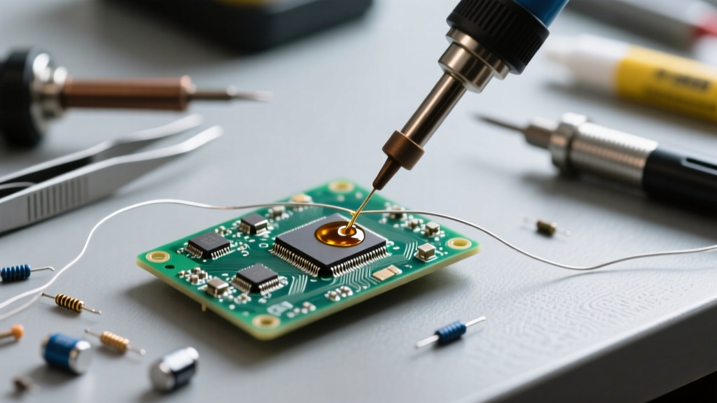
Push the pump’s plunger down until it clicks and locks into the primed position. Hold the pump in your dominant hand (or your non-dominant hand if you are right-handed and prefer to keep your iron hand steady). Apply your fluxed soldering iron tip directly to the joint. For through-hole components, angle the iron at 45 degrees to maximize contact with both the component lead and the plated barrel of the hole.
Step 2: The 3-Second Melt Rule
Watch the solder closely. You are waiting for the solder to transition from a dull, pasty state to a shiny, liquid pool. This should take no more than 2 to 3 seconds. If the solder does not melt within 3 seconds, remove the iron immediately. You are likely dealing with a high-thermal-mass ground plane, and continuing to apply heat will delaminate the PCB.
Step 3: Seal, Trigger, and Release
Once the solder is fully liquid, bring the PTFE tip of the desoldering pump directly over the molten pool. Press the nozzle firmly against the pad to create an airtight seal. Do not use the pump as a lever to pry the component. Keep the pump perfectly vertical. Depress the trigger button smoothly. You will hear a sharp 'thwack' as the vacuum pulls the solder into the cylinder. Wait one full second before pulling the pump away to allow the solder to solidify inside the tip.
Step 4: Inspect and Clean the Through-Hole
After pumping, inspect the hole. If the component lead is still trapped, do not pull it with pliers. Re-apply flux, touch the iron to the joint for one second, and use a pair of tweezers to gently wiggle the lead. If the hole is blocked by residual solder, use a stainless steel through-hole cleaning needle to push the debris out while the solder is molten.
According to the NASA Electronic Parts and Packaging (NEPP) Program workmanship standards, a properly desoldered through-hole should exhibit a clean, unobstructed barrel with no evidence of pad lifting, scorching, or epoxy degradation. If a hole remains partially blocked, rework technicians must use localized bottom-side pre-heating rather than excessive top-side iron dwell times.
Critical Maintenance: Preventing Nozzle Clogs and Spring Fatigue
A desoldering pump is only as effective as its internal seal. Over time, solder vapor and flux residue will accumulate inside the PTFE sleeve and the main cylinder, reducing vacuum pressure.
- Clearing the Nozzle: Most premium pumps feature a removable PTFE tip. Unscrew it and use a brass cleaning brush or a precision drill bit (matched to the nozzle diameter) to push out solidified solder plugs.
- O-Ring Lubrication: The rubber O-ring on the plunger creates the vacuum seal. Every 500 cycles, disassemble the pump, wipe the O-ring clean, and apply a micro-thin layer of silicone grease. Never use petroleum jelly (Vaseline), as petroleum distillates will cause the rubber to swell and degrade, destroying the vacuum seal.
- Spring Replacement: If the pump loses its 'snap' and fails to pull heavy solder joints, the compression spring has fatigued. Replacement springs are available from most tool manufacturers for under $5.
Troubleshooting Desoldering Failures
Even experienced technicians encounter issues when extracting stubborn solder. Use this diagnostic table to identify and resolve common problems.
| Failure Mode | Root Cause | Corrective Action |
|---|---|---|
| Lifted PCB Pad | Mechanical leverage (prying) or excessive heat degrading the epoxy bond. | Keep the pump vertical; use a PCB pre-heater to reduce top-side thermal load. |
| Weak Vacuum / Solder Dribbles | Degraded O-ring, flux buildup in the cylinder, or cracked PTFE tip. | Disassemble, clean the cylinder with isopropyl alcohol, and lubricate the O-ring with silicone grease. |
| Solder Sticking to Nozzle | PTFE tip is scratched, scorched, or missing entirely. | Replace the PTFE tip immediately. Never use a steel file to clean the tip, as it will remove the non-stick coating. |
| Component Lead Snaps | Solder wicked up the lead and solidified, acting as a rigid anchor. | Apply Chip Quik low-melt solder to the joint to reflow the entire lead length simultaneously. |
Expert Tips for Multi-Layer and Ground Plane PCBs
Modern electronics, particularly power supplies and RF modules, utilize multi-layer PCBs with extensive internal copper ground planes. These planes act as massive heat sinks, drawing thermal energy away from your soldering iron tip faster than it can be replenished.
If you are learning how to use a desoldering pump on these complex boards, you must alter your thermal strategy. According to the SparkFun Through-Hole Soldering Guide, attempting to melt a ground-plane connection with a standard 40W iron will result in failure. Instead, utilize a ceramic or infrared PCB pre-heater (such as the Puhui T-8280) to bring the entire board up to 120°C. This reduces the thermal delta, allowing your handheld iron to easily push the joint past the solder's liquidus point without dwelling long enough to scorch the surrounding FR4 material or damage heat-sensitive semiconductor packages.
By combining the right PTFE-tipped tool, aggressive fluxing, and disciplined thermal management, you can master the desoldering pump and execute flawless, damage-free component extractions on any circuit board.