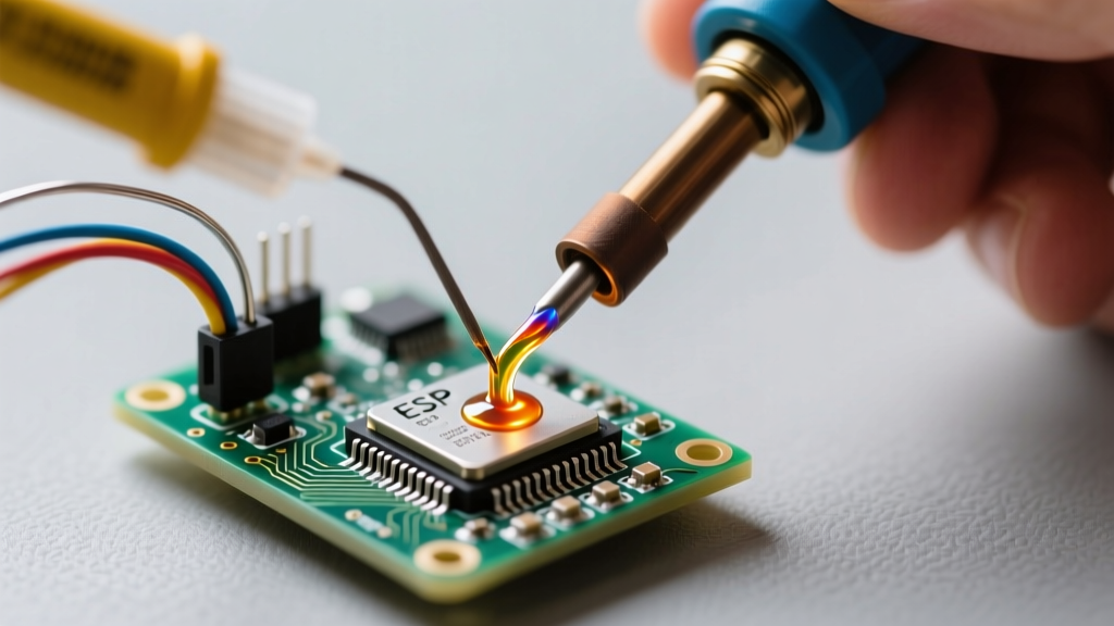

The Thermodynamics of Rework: Why Tool Pairing Matters
When a repair, modification, or component salvage goes wrong, the immediate question every technician faces is: how do you desolder the joint without destroying the printed circuit board (PCB)? Desoldering is fundamentally an exercise in thermal management and mechanical extraction. Unlike soldering, which relies on capillary action to draw molten alloy into a joint, desoldering requires reversing that process while fighting the board's thermal mass and the fragility of copper cladding.
The primary enemy in desoldering is the FR-4 substrate's Glass Transition Temperature (Tg), typically between 130°C and 170°C. Prolonged exposure to temperatures exceeding the Tg causes the epoxy resin to soften, leading to catastrophic pad lifting, via barrel tearing, and internal layer delamination. Therefore, answering 'how do you desolder' correctly requires pairing the exact extraction tool with the appropriate thermal technique for the specific PCB topology and solder alloy involved.
Evaluating the Arsenal: Core Desoldering Profiles
There is no universal desoldering tool. The correct technique depends on whether you are tackling single-layer through-hole components, multi-layer ground planes, or high-density surface-mount devices (SMDs).
Desoldering Braid (Wick) and Flux Synergy
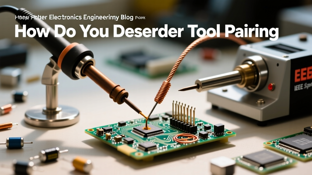
Desoldering braid relies on the capillary action of woven copper wire to absorb molten solder. However, bare copper will not wick effectively without flux to break surface tension and metal oxides. Premium braids like Chemtronics Soder-Wick or MG Chemicals Super Wick come pre-fluxed with either Rosin (R) or No-Clean formulations. Braid is the undisputed champion for flat SMD pads and cleaning up residual solder in through-hole vias, but it acts as a massive heat sink, making it risky for delicate, thin-trace boards if left in place too long.
Manual Vacuum Pumps (Solder Suckers)
Manual pumps, such as the legendary Edsyn Soldapullt or the Engineer SS-02, utilize a mechanical spring-loaded piston to create a sudden vacuum. The technique here requires precise timing: you must heat the joint until the solder is fully liquid, remove the iron, and instantly apply the PTFE (Teflon) tip of the pump to the joint. The PTFE tip is critical; it prevents the extracted solder from adhering to the tool's nozzle. Manual pumps are ideal for rapid removal of bulk solder from large through-hole leads but struggle with high-thermal-mass ground pins.
Motorized Desoldering Stations
For high-volume rework or multi-layer boards with heavy ground planes, motorized vacuum guns like the Hakko FR-301 or the Hakko 808 are mandatory. These tools feature integrated ceramic heating elements and continuous vacuum pumps. The technique involves encasing the component lead in the heated nozzle, allowing the internal thermal mass to liquefy the solder deep inside the plated through-hole (PTH), and then triggering the vacuum to pull the solder out in one fluid motion. This minimizes Z-axis thermal expansion stress on the via barrels.
Convective Hot Air Rework Stations
When dealing with multi-pin SMDs, QFNs, or BGAs, point-contact tools fail. Hot air stations, such as the Quick 861DW, use convective heat to raise the temperature of the entire component footprint simultaneously. The technique requires a delicate balance of airflow (to prevent blowing away smaller adjacent components) and temperature profiling to ensure the solder paste reaches its liquidus state across all pads at the exact same moment.
The Tool & Technique Matrix: Matching Gear to the Board
To systematically answer how do you desolder across different scenarios, refer to this pairing matrix. This framework prevents the most common rework failure modes.
| Tool Category | Ideal PCB / Component Type | Target Temp (SAC305 Lead-Free) | Primary Risk / Failure Mode | Pro Technique Tip |
|---|---|---|---|---|
| Desoldering Braid | SMD Pads, Vias, Fine-Pitch ICs | 350°C - 380°C | Pad lifting, trace scorching | Use a silicone heat shield; never drag dry braid across pads. |
| Manual Vacuum Pump | Single/Double-layer Through-Hole | 360°C | Incomplete extraction, pad tear | Apply fresh leaded solder first to lower the alloy melting point. |
| Motorized Vac Gun | Multi-layer PTHs, Heavy Ground Pins | 380°C - 400°C | Via barrel separation, nozzle clog | Use a board pre-heater to reduce the thermal delta (ΔT). |
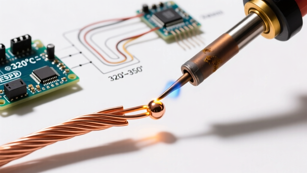
| Hot Air Station | QFN, SOIC, BGA, SMD Arrays | 320°C - 360°C (Air Temp) | Component melting, pad cratering | Use Kapton tape to mask surroundings; apply tack flux before heating. |
Step-by-Step Protocol: Extracting Stubborn Through-Hole Components
One of the most frequent challenges in electronics repair is removing a multi-pin through-hole component from a board with internal ground planes. The internal copper layers act as massive heat sinks, drawing thermal energy away from the joint. If you simply ask 'how do you desolder' and apply brute heat, you will destroy the board. Follow this expert protocol:
- The Alloy Dilution Trick: Modern electronics use Lead-Free solder (like SAC305, melting at ~217°C). Before attempting extraction, melt a generous amount of traditional 63/37 Leaded solder (melting at 183°C) into the joint. This mixes the alloys, drastically lowering the overall melting point and improving flow characteristics.
- Flux Flooding: Apply a high-quality, viscous liquid flux (such as Amtech NC-559 or Chip Quik SMD291AX) to the pins. Flux prevents oxidation during the extended heating time required for high-mass joints.
- Sequential Heating and Extraction: Using a motorized desoldering gun or a high-wattage iron (minimum 80W to prevent tip temperature crash) paired with a manual pump, heat each pin individually. Wait for the solder to 'flash' (turn completely liquid and shiny) before applying vacuum.
- Lead Liberation: After the bulk solder is removed, do not pull the component. Use a pair of fine tweezers to gently wiggle each lead while briefly touching it with the iron to break any remaining micro-bridges inside the via.
Navigating High Thermal Mass: The Role of Pre-Heating
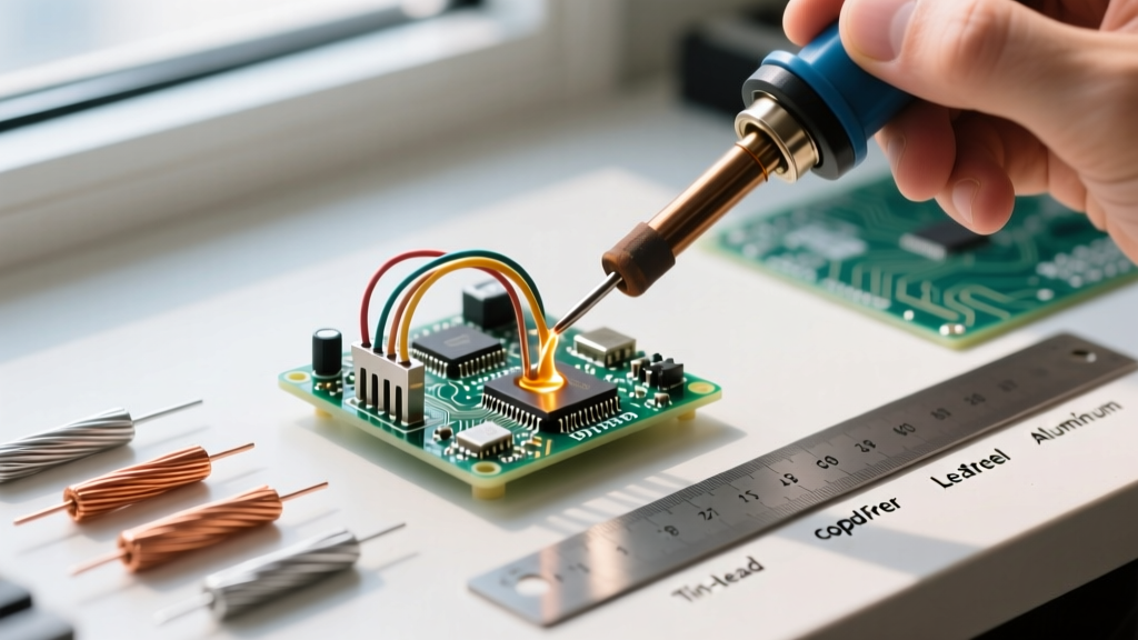
According to the rework guidelines outlined in the IPC-7711/7721 standards for rework and modification, minimizing the thermal gradient between the top and bottom of a PCB is critical for preserving the structural integrity of plated through-holes. When a board features heavy copper pours or aluminum core substrates (MCPCBs), top-side heating alone will cause the Z-axis Coefficient of Thermal Expansion (CTE) of the FR-4 to expand faster than the copper barrel, resulting in internal 'barrel tears' that sever electrical connections on inner layers.
To combat this, pair your top-side desoldering tool with an IR or quartz board pre-heater (like the Hakko FR-830). By bringing the ambient temperature of the entire PCB up to 100°C - 120°C from below, your top-side iron or hot air tool only needs to bridge a 150°C gap to reach liquidus, rather than a 300°C gap. This drastically reduces dwell time and eliminates pad cratering.
Post-Extraction Pad Rehabilitation
Knowing how do you desolder is only half the battle; preparing the site for the new component is equally vital. Once the component is removed, the pads will likely be covered in oxidized, uneven solder residue.
- Flatten the Pads: Use a wide, flat desoldering braid paired with a chisel-tip iron set to 350°C. Apply downward pressure gently to wick away the remaining solder, leaving the pad perfectly flat. A raised pad will prevent the new component from seating correctly, leading to tombstoning or open circuits.
- Chemical Cleaning: Scrub the area with 99% Isopropyl Alcohol (IPA) and an ESD-safe brush to remove activated flux residues, which can cause parasitic capacitance or electrochemical migration over time.
- Via Verification: Inspect the cleaned vias under a microscope. If a via is blocked by a 'solder icicle' inside the barrel, use a precision stainless steel dental pick or a specialized via cleaning drill to gently clear the obstruction before installing the replacement part.
Expert Insight: Never use a fiberglass scratch pen on bare copper pads after desoldering unless absolutely necessary to remove severe oxidation. Fiberglass will micro-scratch the copper, removing the vital immersion silver or ENIG finish and exposing raw copper to immediate oxidation, which will severely compromise the wetting of your new solder joint. Always rely on chemical flux and thermal energy to clean the pad.
Mastering how do you desolder effectively requires moving beyond the basic solder sucker and embracing a systematic approach to thermal dynamics. By pairing the correct extraction technology with alloy dilution, pre-heating, and meticulous pad rehabilitation, you can rework even the most complex, high-density PCBs with factory-level reliability. For further reading on thermal limits and acceptable rework criteria, technicians should consult the NASA Electronic Parts and Packaging (NEPP) Program workmanship manuals, which provide exhaustive visual standards for via and pad integrity post-desoldering.