
What Exactly is a Cold Solder Joint?
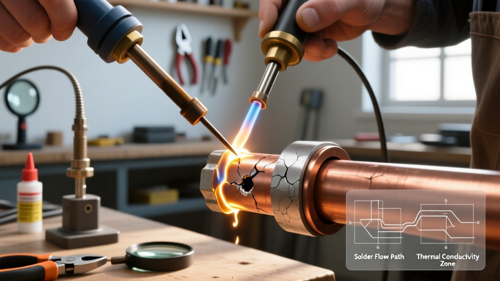
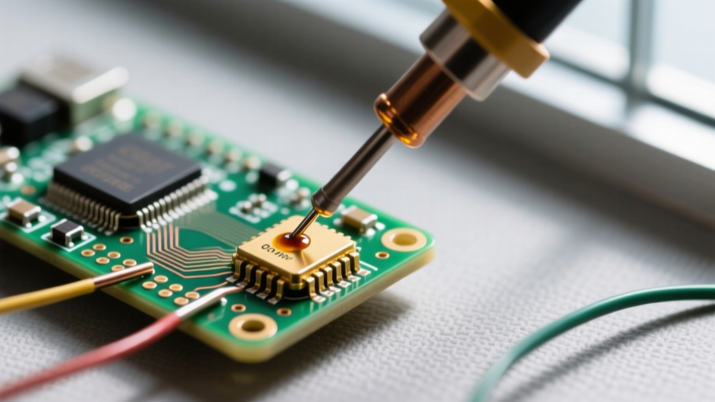
In the world of electronics assembly, few defects are as notorious or as misunderstood as the cold solder joint. Contrary to what the name implies, cold soldering does not mean the solder was applied at room temperature. Rather, it refers to a joint where the solder alloy failed to reach its proper liquidus temperature or lacked sufficient thermal energy to properly 'wet' the metal surfaces. As of 2026, despite advancements in automated reflow ovens, cold soldering remains one of the most common failure points in hand-assembled PCBs and DIY microcontroller projects.
When a joint is properly heated, the molten solder dissolves a microscopic layer of the copper pad and component lead, forming a robust Intermetallic Compound (IMC) layer—specifically Cu6Sn5 in tin-based solders. A cold joint fails to form this IMC layer. The result is a weak mechanical bond and a high-resistance electrical connection that can lead to intermittent faults, thermal runaway, or total device failure.
Visual Diagnostics: The Anatomy of a Bad Joint
Identifying cold soldering defects requires training your eye to look at the geometry and surface texture of the solder fillet. According to the IPC J-STD-001 standard, a proper through-hole solder joint must exhibit a concave fillet with a wetting angle of less than 90 degrees. Here is how to differentiate between joint types:
| Joint Type | Visual Appearance | Surface Texture | Wetting Angle |
|---|---|---|---|
| Ideal Joint | Concave, smooth slope from lead to pad | Shiny, mirror-like (leaded) or smooth matte (lead-free) | < 90° |
| Cold Joint | Convex, lumpy, resembles a ball resting on the pad | Dull, grainy, frosty, or orange-peel texture | > 90° |
| Disturbed Joint | Similar to cold, but with visible ridges or 'frost lines' | Grainy with distinct crystalline fracture lines | Variable |
| Starved Joint | Concave but does not reach the top of the barrel | Smooth but incomplete coverage | < 90° |
The 3 Primary Culprits Behind Cold Soldering
Before you can fix a cold joint, you must understand why it happened. Beginners usually fall victim to one of three specific errors:
1. Incorrect Iron Temperature and Thermal Recovery
Setting your iron to the exact melting point of the solder is a critical mistake. Solder melts at 183°C (Sn63/Pb37) or 217°C (SAC305 lead-free), but the iron must supply enough excess heat to overcome the thermal mass of the PCB ground planes. If your iron is set to 200°C for leaded solder, the tip temperature will plummet the moment it touches a copper pad, resulting in a cold joint. The Fix: Set your station to 320°C–350°C for leaded solder, and 350°C–380°C for lead-free alloys.
2. Poor Tip Geometry Selection
Using a fine conical tip (like a standard B2 tip) for large ground pads is a recipe for cold soldering. Conical tips have a tiny surface area, meaning they transfer heat incredibly slowly. The Fix: Switch to a chisel tip (e.g., Hakko T12-D24 or Pinecil TS-C4). The flat blade maximizes surface area contact, transferring thermal energy into the pad up to 4x faster than a conical tip.
3. Flux Exhaustion and Oxidation
Flux is the chemical cleaner that removes oxidation, allowing the solder to wet the metal. Most rosin-based fluxes activate around 150°C and burn off completely by 250°C. If you heat the pad for 5 seconds before applying solder, the flux in the solder wire vaporizes before it can do its job, leaving oxidized metal that rejects the molten alloy.
Step-by-Step Walkthrough: Reworking a Cold Solder Joint
Fixing a cold joint is not as simple as just melting it again. You must introduce fresh materials to restore the chemical and thermal balance. Follow this exact procedure:
- Clean the Area: Wipe the joint and surrounding PCB area with 99% Isopropyl Alcohol (IPA) and a lint-free swab to remove surface oils and old flux residue.
- Apply External Flux: Dispense a small bead of tacky flux (such as Amtech NC-559-V2-TF, approx. $28 per syringe) or brush on a liquid flux like Kester 951 over the cold joint. This is non-negotiable; the joint will not re-flow properly without it.
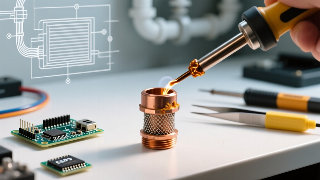
- Add Fresh Solder: Do not just melt the existing solder. Touch a small amount of fresh, high-quality solder wire (0.8mm diameter is ideal for through-hole) to the joint. The fresh solder brings new flux and fresh tin/lead alloys to facilitate the IMC layer formation.
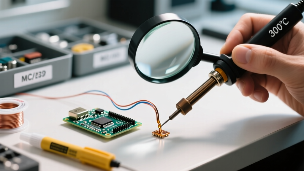
- The 'Feed and Heat' Technique: Place your chisel tip so it touches BOTH the component lead and the PCB pad simultaneously. Hold for 1 second, then feed the solder wire into the opposite side of the joint. The solder should flash and flow smoothly into a concave fillet within 2 to 3 seconds.
- Remove and Cool: Remove the solder wire first, then the iron. Let the joint cool naturally for 3-5 seconds. Do not blow on it; forced cooling can cause micro-fractures (disturbed joints).
- Final Cleanup: Once cooled, clean the residual tacky flux with IPA and a stiff brush to prevent long-term corrosion.
Gear Guide: Choosing the Right Iron to Prevent Cold Joints
Your soldering station's thermal recovery rate is your first line of defense against cold soldering. Here is how the top beginner-to-pro irons compare in 2026:
- Pinecil V2 (~$26): The undisputed budget king. Powered by a 65W USB-C PD supply, it uses T12-style tips and recovers from thermal drops in under 2 seconds. Ideal for beginners who want pro-level thermal mass transfer without the pro-level price tag.
- Hakko FX-888D (~$110): The legacy workhorse. It uses T18 tips, which have slightly slower thermal recovery than T12s, but the 70W ceramic heater is incredibly reliable. If you are soldering large ground planes, ensure you use the FX-888D with a D24 chisel tip to avoid cold joints.
- Weller WE1010 (~$135): Features a 70W heater and ET series tips. It boasts excellent tip-to-handle heat transfer, making it highly resistant to cold soldering on multi-layer PCBs.
Advanced Troubleshooting: Finding Hidden Cold Joints
Sometimes, a cold joint looks perfectly shiny and concave but still fails electrically. This often happens with lead-free SAC305 solder, which naturally dries matte and can hide grainy cold fractures. To find these hidden defects:
The Multimeter 'Wiggle' Test
Set your digital multimeter to continuity mode (the beep setting). Place one probe on the component lead and the other on the nearest trace. While monitoring the meter, gently push the component with a non-conductive spudger. If the multimeter beeps intermittently or the resistance jumps from 0.1Ω to 5Ω, you have a hidden cold or cracked joint.
Thermal Imaging
A cold joint has higher electrical resistance than a good joint. When current flows through the circuit, Ohm's law dictates that the higher resistance joint will dissipate more power as heat. Using a smartphone thermal camera attachment (like the FLIR One or InfiRay P2), power on your PCB and look for localized hot spots at the solder joints. A joint glowing 10°C hotter than its neighbors is likely a high-resistance cold joint.
Mastering the identification and repair of cold soldering joints is a rite of passage for every electronics enthusiast. By respecting the metallurgy, using the correct tip geometry, and never skipping the external flux step, you will build connections that last a lifetime. For further reading on industry-standard defect identification, refer to the comprehensive visual guides in SparkFun's through-hole soldering tutorial.