
The "Soldering vs Soldering" Dilemma: Soft vs. Hard Techniques
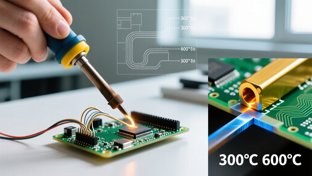
When engineers, HVAC technicians, and DIYers type the seemingly redundant phrase soldering vs soldering into search engines, they are almost always attempting to resolve the confusion between two fundamentally different metallurgical processes: soft soldering and hard soldering (technically known as brazing or silver soldering). The American Welding Society (AWS) strictly defines the 450°C (842°F) thermal threshold as the absolute dividing line between these methods. Below this temperature, you are soft soldering (typical for PCBs and delicate electronics). Above it, you are hard soldering or brazing (used for structural metals, HVAC refrigerant lines, and high-stress mechanical joints).
As of 2026, the material science behind both techniques has evolved significantly, with new bismuth-doped low-temperature alloys disrupting traditional soft soldering, and advanced flux-cored silver alloys streamlining hard soldering. This guide breaks down the exact metallurgical differences, thermal profiles, and troubleshooting frameworks for both disciplines.
Metallurgical Comparison Matrix
| Feature | Soft Soldering (Electronics/Micro) | Hard Soldering / Brazing (Structural) |
|---|---|---|
| Temperature Threshold | Below 450°C (842°F) | Above 450°C (842°F) |
| Standard Alloys (2026) | SAC305, SAC-Bi, Sn63/Pb37 | BCuP-5 (15% Ag), BAg-24 (50% Ag) |
| Melting Point Range | 138°C – 225°C | 600°C – 850°C |
| Flux Chemistry | Rosin (RMA), No-Clean, Water-Soluble | Borax, Fluoride-based, Boric Acid |
| Joint Mechanism | Surface wetting & thin IMC layer | Deep capillary action & alloy diffusion |
| Tensile Strength | Low to Moderate (20 - 50 MPa) | High (300 - 800+ MPa) |
Soft Soldering: Electronics and Micro-Joining
Alloy Specifics and Thermal Profiles
Soft soldering relies on the formation of an Intermetallic Compound (IMC) layer—typically Cu6Sn5 and Cu3Sn phases—between the copper substrate and the tin-based alloy. A properly formed IMC layer is incredibly thin, ideally between 1 and 3 micrometers. If the thermal profile exceeds the recommended dwell time, the IMC layer grows too thick, resulting in a brittle joint prone to micro-fractures under thermal cycling.
While legacy Sn63/Pb37 (Tin/Lead) eutectic solder melts sharply at 183°C, the modern industry standard is SAC305 (96.5% Tin, 3.0% Silver, 0.5% Copper), which has a liquidus point of 217°C–220°C. In 2026, we are seeing a massive shift toward SAC-Bi (Tin-Silver-Copper-Bismuth) alloys. The addition of bismuth drops the melting point closer to 170°C, drastically reducing thermal warpage on ultra-thin BGA substrates and flexible PCBs.
According to the latest IPC standards, proper wetting requires a contact angle of less than 90 degrees, with a visible, smooth fillet climbing the component lead. A dull, grainy appearance indicates the joint was disturbed during the plastic (pasty) phase of the cooling cycle.
Hard Soldering (Brazing): Structural and High-Stress Joints
Silver Alloys and Capillary Action Physics
Hard soldering, or brazing, does not just wet the surface; it relies on capillary action to draw the molten filler metal deep into the joint interface. For this to occur, the radial clearance between the mating parts must be meticulously controlled. The optimal clearance for silver-based braze alloys (like BCuP-5, which contains 15% Silver, 80% Copper, and 5% Phosphorus) is exactly 0.002 to 0.005 inches. If the gap is wider than 0.005 inches, capillary force drops off exponentially, resulting in void-filled, structurally compromised joints.
Because brazing temperatures exceed 640°C, base metals will rapidly oxidize. Fluoride-based and borax fluxes are mandatory to dissolve these oxides. Indium Corporation and other metallurgical experts note that failing to quench and clean borax-based flux residues after brazing will lead to severe galvanic corrosion in high-humidity environments, eventually destroying the joint from the inside out.
Troubleshooting Common Joint Failures
Whether you are working with a 60W micro-pencil iron or an oxy-acetylene torch, understanding failure modes is critical for quality control.
Soft Soldering Defects
- Cold Joints: Characterized by a lumpy, matte-grey appearance. Cause: Insufficient thermal transfer to the pad, preventing the flux from fully activating and the IMC layer from forming. Fix: Increase iron tip mass or dwell time; ensure the tip is tinned for optimal thermal conductivity.
- Dewetting: The solder balls up and refuses to spread across the copper pad. Cause: Severe oxidation or organic contamination on the base metal. Fix: Mechanical abrasion (fiberglass pen) followed by isopropyl alcohol cleaning and fresh RMA flux application.
- Tombstoning (Reflow): Surface mount components stand on one end. Cause: Uneven heating across the PCB causing one pad's solder paste to reach liquidus before the other, pulling the component via surface tension. Fix: Adjust the reflow oven's soak zone profile to ensure thermal equilibrium before the reflow spike.
Hard Soldering Defects
- Flux Inclusions: Trapped glassy slag inside the brazed joint. Cause: Overheating the flux until it becomes viscous, or applying the filler rod directly onto the flux rather than the heated base metal. Fix: Apply heat evenly to the base metal and touch the rod to the joint edge, letting capillary action pull it in.
- Base Metal Erosion: The base copper or steel physically thins out near the joint. Cause: Excessive torch dwell time at extreme temperatures, causing the base metal to dissolve into the molten silver alloy. Fix: Use a larger, cooler flame envelope and keep the torch moving.
Frequently Asked Questions (FAQ)
Why is "soldering vs soldering" a common search query?
The phrase "soldering vs soldering" is a frequent search anomaly. Users typing this are usually trying to compare two distinct subsets of the craft but use the same root word. Most commonly, they are looking for Soft Soldering vs. Hard Soldering (as detailed above), Lead vs. Lead-Free Soldering, or Wave Soldering vs. Reflow Soldering in PCB manufacturing contexts.
Can I use hard soldering (brazing) alloys to repair a heavy-duty PCB trace?
No. The thermal mass and temperatures required to melt BCuP or BAg alloys (600°C+) will instantly delaminate the FR4 fiberglass substrate of a PCB, burn away the copper trace, and destroy nearby components. For heavy-duty PCB repairs requiring high current capacity, use soft soldering with a high-tin alloy (like Sn96.5/Ag3.5) and reinforce the trace with bare copper wire.
Is acid flux ever acceptable for electronics soft soldering?
Absolutely not. Acid fluxes (zinc chloride or ammonium chloride) are designed for plumbing and sheet metal. They are highly corrosive and will cause rapid dendritic growth and short circuits on a PCB. Only use Rosin (R, RMA, RA) or specialized No-Clean/Water-Soluble organic fluxes for electrical work.
How do I choose the right soldering iron tip for soft soldering?
Match the tip's thermal mass to the joint's ground plane. For 0402 SMD components, use a micro-conical (e.g., 0.4mm) tip. For heavy through-hole capacitors connected to large ground planes, use a chisel or bevel tip (e.g., 3.2mm - 5.0mm) to maximize surface contact area and prevent the ground plane from acting as a heat sink, which causes cold joints.