
Introduction: The Metallurgy of Joining
Whether you are assembling a custom PCB, repairing HVAC refrigerant lines, or fabricating a structural steel chassis, understanding the difference between soldering, welding, and brazing is the most critical decision you will make in your workflow. Confusing these processes leads to catastrophic joint failures, compromised electrical conductivity, or blown base materials. While all three methods utilize a filler metal to join two workpieces, the underlying metallurgy, thermal dynamics, and execution steps are vastly different.
In this step-by-step tutorial, we will break down the exact thermal thresholds, equipment costs, and execution protocols for each method, providing you with a practical decision framework and actionable instructions for 2026 workshop standards.
Step 1: The Decision Matrix (Choosing Your Process)
Before striking an arc or heating an iron, you must evaluate your base material, required joint strength, and thermal tolerance. The fundamental difference between soldering, welding, and brazing lies in whether the base metal melts and the temperature threshold of the filler.
| Parameter | Soldering | Brazing | Welding |
|---|---|---|---|
| Temperature | Below 450°C (840°F) | Above 450°C (840°F) | Above 1500°C (2732°F) |
| Base Metal Melts? | No | No | Yes |
| Joint Mechanism | Surface wetting / Adhesion | Capillary action | Coalescence / Fusion |
| Typical Strength | Low to Medium (Electrical focus) | High (Structural & Pressure) | Very High (Matches base metal) |
| Equipment Cost | $50 - $300 | $300 - $1,500 | $800 - $5,000+ |
Pro-Tip: If your project involves delicate electronics or heat-sensitive components, soldering is your only viable option. If you need to join dissimilar metals (like copper to steel) without melting the base, choose brazing. If you need maximum structural load-bearing capacity on thick steel, choose welding.
Step 2: Executing a Soldered Joint (Electronics & Low-Temp Copper)
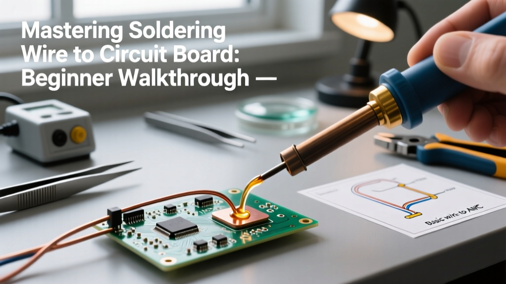
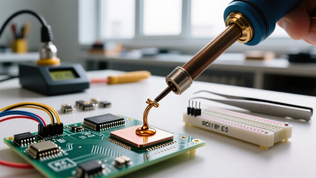
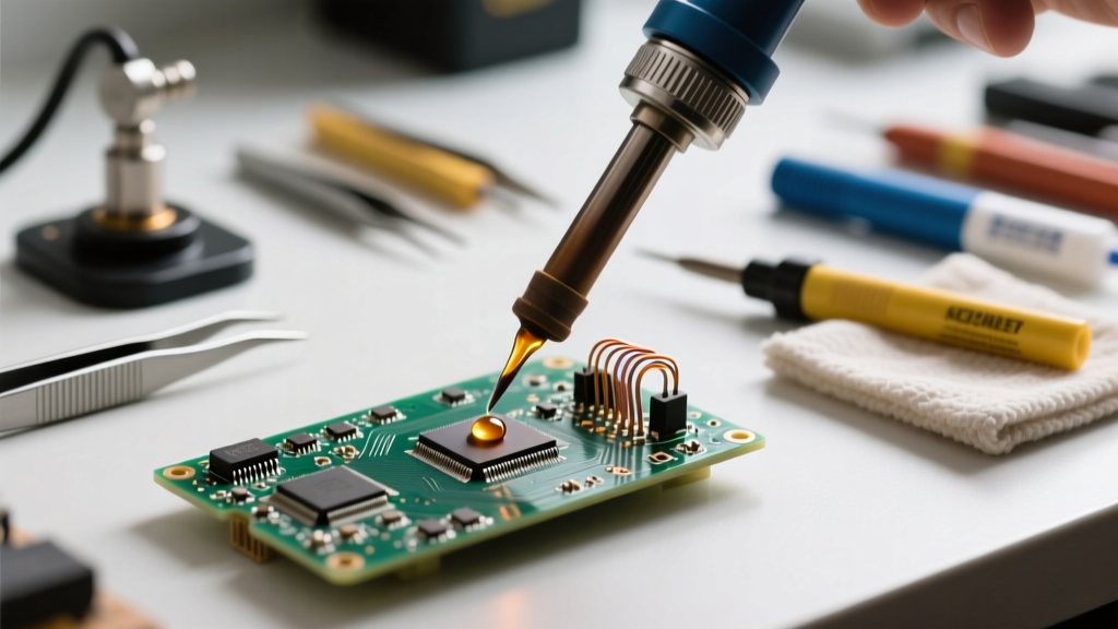
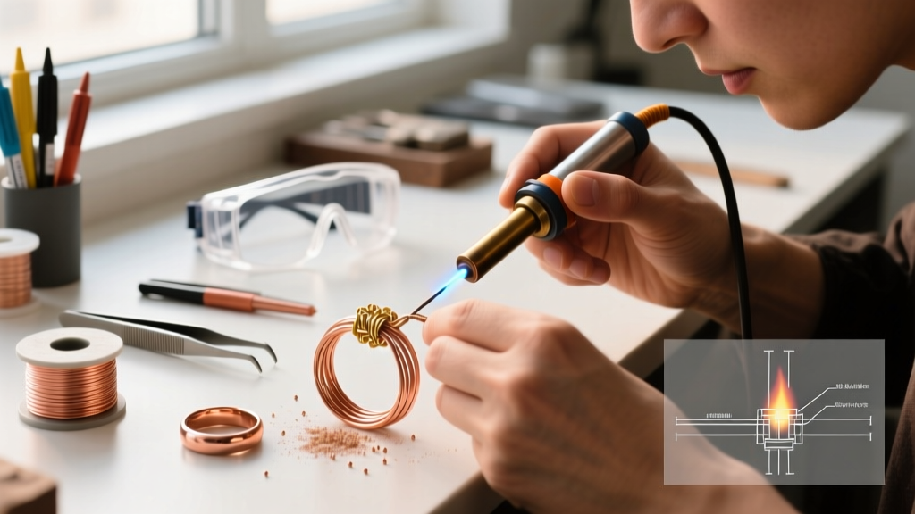
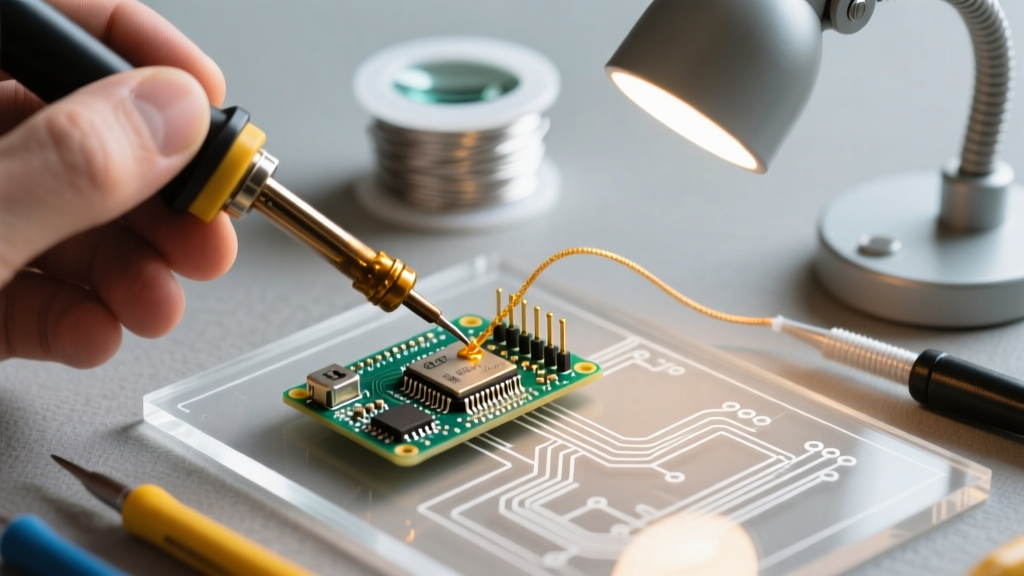
Soldering relies on surface wetting. The filler metal (solder) melts and flows over the base metal via capillary action and metallurgical bonding, but the base metal remains solid. For electronics, we follow the stringent visual and mechanical standards set by IPC (Association Connecting Electronics Industries).
Material & Tool Selection
- Station: Hakko FX-888D Digital Soldering Station (Approx. $115). Use a T18-D24 chisel tip for optimal thermal transfer to through-hole pads.
- Filler Metal: Kester 63/37 Sn/Pb Eutectic ($35/lb) for hobbyist/legacy work, or SAC305 (Sn96.5/Ag3.0/Cu0.5) lead-free alloy ($60/lb) for RoHS-compliant commercial boards.
- Flux: No-Clean Rosin-based flux pen (e.g., MG Chemicals 8341).
Step-by-Step Procedure
- Prep & Tin: Clean the PCB pads with 99% isopropyl alcohol. Apply a micro-layer of solder to the iron tip to prevent oxidation.
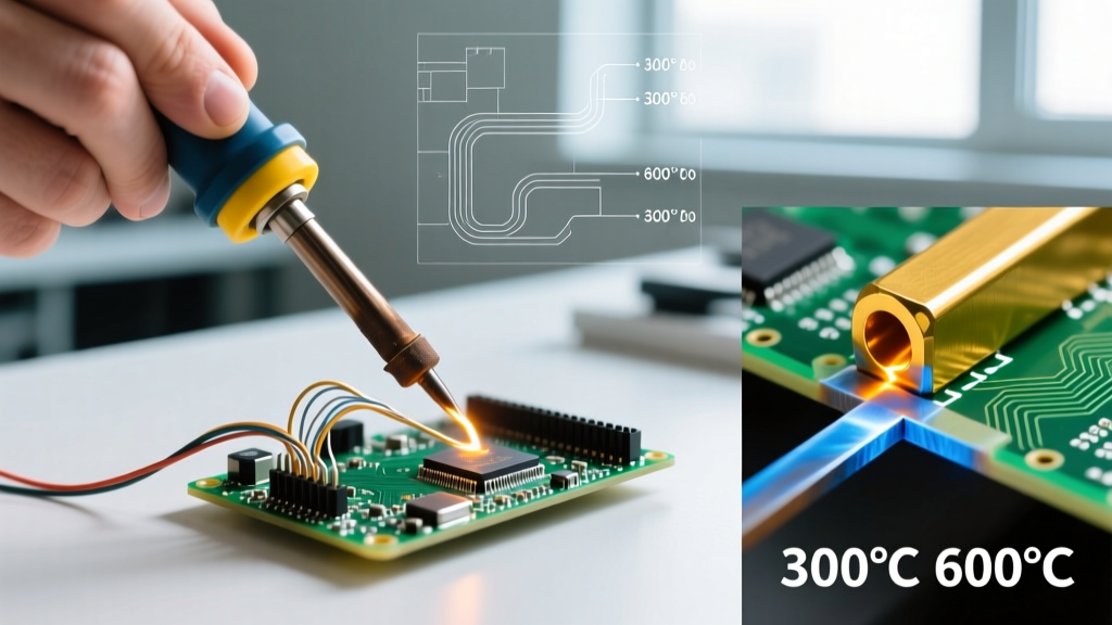
- Thermal Transfer: Set the Hakko to 350°C for 63/37 leaded, or 380°C for SAC305 lead-free. Place the flat of the chisel tip so it simultaneously touches the component lead and the copper pad.
- Feed the Solder: Wait exactly 1.5 to 2 seconds for the joint to reach thermal equilibrium. Feed the solder wire into the joint, not the iron tip. The flux should activate, bubbling slightly as it strips microscopic oxides.
- Cooling: Remove the solder, then the iron. Let the joint cool naturally for 3 seconds. A disturbed joint during the plastic phase will result in a fractured, high-resistance 'cold' joint.
Step 3: Executing a Brazed Joint (HVAC, Brass, & Structural Copper)
Brazing operates above 450°C but below the melting point of the base metals. It relies heavily on precise joint clearances and capillary action to draw the filler deep into the joint space. According to the engineering guidelines published by the Harris Products Group, proper clearance is the single most critical factor in brazing success.
Material & Tool Selection
- Heat Source: Smith Heavy-Duty Oxy-Acetylene Torch Setup (Approx. $450). Use a #3 or #4 welding tip for a broad, neutral flame.
- Filler Metal: Harris Safety-Silv 45 (45% Silver, Cadmium-Free). Costs roughly $120 for a 1oz tube or $80/lb for rod. The high silver content ensures excellent flow on copper-to-brass transitions.
- Flux: Stay-Silv White Flux paste, active between 565°C and 870°C.
Step-by-Step Procedure
- Mechanical Cleaning: Abrade the copper pipe and brass fitting with 120-grit emery cloth until bright. Wipe with a clean rag. Oxide layers will block capillary flow entirely.
- Flux Application: Apply a thin, even coat of Stay-Silv White Flux to both mating surfaces. Assemble the joint.
- Heating the Base Metal: Ignite the torch and adjust to a neutral flame. Sweep the flame back and forth across the base metals, keeping the inner cone at least 2 inches away from the joint to avoid localized melting. Use a Tempilstik (temperature-indicating crayon) rated for 1100°F (593°C) on the opposite side of the joint to verify when capillary temperature is reached.
- Capillary Draw: Once the flux turns clear and glassy, touch the Safety-Silv 45 rod to the joint edge. If the base metal is hot enough, the rod will instantly melt and be sucked into the joint via capillary action. Keep the flame on the base metal, not the rod.
- Quench & Clean: Allow the joint to cool until the black glassy flux residue cracks, then quench with a damp rag to pop the flux off and reveal a shiny, continuous silver fillet.
Step 4: Executing a Welded Joint (Structural Steel & Aluminum)
Welding is the only process where the base metals themselves are melted and fused together, often with a compatible filler metal added to the molten puddle. The American Welding Society (AWS) classifies this as coalescence. For this tutorial, we will focus on Gas Tungsten Arc Welding (GTAW/TIG), which offers the highest precision for critical joints.
Material & Tool Selection
- Machine: Lincoln Electric Power TIG 200 (Approx. $1,200). Offers high-frequency start and AC/DC capabilities.
- Tungsten Electrode: 2% Ceriated (Grey tip), 1/16" diameter for DCEN steel welding up to 125 amps.
- Filler Metal: ER70S-2 mild steel TIG rod, 1/16" diameter.
- Shielding Gas: 100% Argon, set to 15-20 Cubic Feet per Hour (CFH).
Step-by-Step Procedure
- Tungsten Prep: Grind the tungsten longitudinally (parallel to its length) using a dedicated 220-grit diamond wheel. Grinding circumferentially will cause the arc to wander and destabilize the puddle.
- Joint Fit-Up: For a butt weld on 1/8" (3mm) steel, set a root gap of 1/16" and tack weld both ends. The amperage rule of thumb for TIG is 1 amp per 0.001" of material thickness (approx. 125 amps for 1/8" steel).
- Arc Initiation: Hold the torch at a 15-degree push angle. Press the foot pedal to initiate the high-frequency arc without touching the tungsten to the workpiece.
- Puddle Control & Dabbing: Melt the leading edge of the joint until a molten puddle forms (about the size of a dime). Dip the ER70S-2 filler rod into the leading edge of the puddle, withdraw it, move the torch forward by one puddle-width, and repeat. This 'dab and step' rhythm ensures uniform penetration and bead profile.
- Crater Fill: At the end of the weld, do not simply lift the torch. Slowly release the foot pedal to decrease the amperage over 2 seconds, filling the final crater to prevent stress cracks.
Troubleshooting Common Edge Cases & Failure Modes
Even with the correct process selection, execution errors will compromise your work. Here is how to diagnose and fix the most common failures across all three disciplines:
- Cold Solder Joints (Soldering): The joint looks dull, grainy, or bulbous. Cause: Insufficient heat transfer to the pad, or moving the component before the solder solidified. Fix: Re-flux the joint, reheat with a clean iron tip until the solder flows glossy, and hold still for 3 seconds.
- Flux Inclusions & Porosity (Brazing): The brazed joint leaks under pressure or shows pitting. Cause: The joint clearance was too tight (below 0.001"), preventing flux from escaping and blocking filler metal entry. Fix: Machine or sand the fitting to achieve the optimal 0.002" to 0.005" radial clearance before re-brazing.
- Weld Undercut & Porosity (Welding): A groove melts into the base metal adjacent to the weld bead, or tiny gas pockets form inside the weld. Cause: Undercut is caused by travel speed being too fast or amperage too high. Porosity is caused by loss of argon shielding gas or contaminated base metal. Fix: Reduce amperage by 10%, slow your travel speed, and ensure the argon post-flow is set to at least 5 seconds to protect the cooling crater.
Conclusion
Mastering the difference between soldering, welding, and brazing is not just about memorizing temperatures; it is about understanding how thermal energy interacts with metallurgical structures. By matching the correct process to your specific mechanical, electrical, and environmental requirements—and executing the steps with precision tooling and proper filler alloys—you ensure joints that are safe, conductive, and structurally sound for decades to come.