
Beyond the Dial: The Thermodynamics of Advanced Soldering
For hobbyists, setting a soldering station to 350°C and applying heat until the metal flows is often sufficient. However, in advanced PCB rework, aerospace electronics, and high-density 2026 micro-BGA assemblies, this brute-force approach leads to catastrophic failure modes like pad cratering, flux charring, and latent intermetallic compound (IMC) fracturing. True mastery of the soldering wire melting temperature requires a deep understanding of alloy phase transitions, thermal mass compensation, and flux activation kinetics.
Understanding the exact soldering wire melting temperature is not just about reading the label on the spool; it is about managing the delta between your iron tip temperature, the thermal mass of the copper pad, and the specific solidus-to-liquidus transition of the alloy you are using.
Phase Transitions: Solidus, Liquidus, and the Plastic Range
The most critical concept in advanced soldering is the distinction between eutectic and non-eutectic alloys. Eutectic alloys transition directly from solid to liquid at a single temperature. Non-eutectic alloys possess a 'plastic range'—a temperature gap where the alloy is in a semi-solid, paste-like state. Disturbing a joint during this plastic range guarantees a grainy, fractured cold joint.
| Alloy Designation | Composition | Solidus (°C) | Liquidus (°C) | Plastic Range | Primary Application |
|---|---|---|---|---|---|
| Sn63/Pb37 | 63% Sn, 37% Pb | 183 | 183 | 0°C (Eutectic) | Legacy/Aerospace (RoHS exempt) |
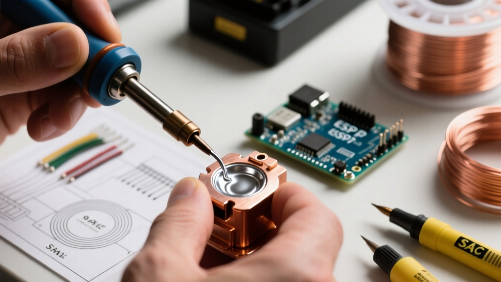
| SAC305 | 96.5% Sn, 3% Ag, 0.5% Cu | 217 | 220 | 3°C | Standard Lead-Free SMT |
| SAC405 | 95.5% Sn, 4% Ag, 0.5% Cu | 217 | 224 | 7°C | High-Reliability Automotive |
| Sn96.5/Ag3.5 | 96.5% Sn, 3.5% Ag | 221 | 224 | 3°C | High-Temp Step Soldering |
| Sn95/Sb5 | 95% Sn, 5% Sb | 232 | 240 | 8°C | High-Temp Filter Soldering |
Data sourced from industry-standard metallurgical profiles. For comprehensive alloy phase diagrams, refer to the Indium Corporation solder alloy database.
The Flux Activation Window vs. Melting Point
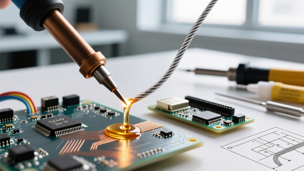
A common failure in advanced rework is applying heat so rapidly that the soldering wire melting temperature is reached before the flux has fully activated. Fluxes require a specific thermal soak to volatilize solvents and break down metal oxides.
The Thermal Lag Rule: If you are using a SAC305 wire (liquidus 220°C) with a ROL0 (No-Clean) flux, the flux activation typically begins around 150°C and peaks at 180°C. If your iron tip is set to 400°C and applied directly to a heavy ground plane, the localized solder may hit 220°C in 1.5 seconds, but the flux core will flash-boil and spatter before it can reduce the copper oxides, resulting in poor wetting and severe solder balling.
Optimizing the Thermal Ramp
- Pre-heat Phase: Use a hot air pencil at 150°C to bring the localized PCB area to flux activation temperature before introducing the soldering iron.
- Wire Feeding: Never melt the wire directly on the iron tip. Apply the iron to the pad/component lead, and feed the wire into the pad-to-lead interface. The thermal conductivity of the molten flux will bridge the gap and accelerate wetting.
Thermal Mass and Tip Selection in 2026
As component densities increase and 01005 passives sit adjacent to massive 14-layer ground planes, the soldering wire melting temperature becomes irrelevant if your tooling cannot deliver the necessary joules of energy. A 0.5mm conical tip set to 400°C will fail to melt SAC305 on a heavy via because the thermal mass of the copper drains heat faster than the tip's heater can replenish it.
Advanced Station and Tip Pairings
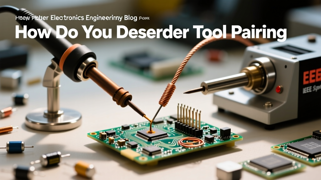
In 2026, active-tip technology remains the gold standard for managing heavy thermal loads without resorting to destructive tip temperatures.
- JBC CD-2BQF with C245-07 (Chisel 2.2mm): The heater is integrated directly into the tip. Priced around $1,150 for the station and $50 per tip, it recovers from a 220°C liquidus drop in under 0.8 seconds. Ideal for multi-layer power planes.
- Weller WX2 with WXP120 (LT 1.6mm Bevel): Excellent for mid-mass SMD rework. The bevel geometry increases surface area contact, ensuring the pad reaches the soldering wire melting temperature uniformly before the flux burns off.
- Hakko FX-951 with T12-C4: A reliable workhorse, though thermal recovery on massive ground planes requires a dwell time increase of 1.5 to 2.5 seconds compared to JBC systems.
Troubleshooting Matrix: Melting Temperature Edge Cases
When rework fails, the root cause is almost always a mismanagement of the thermal profile relative to the alloy's specific melting characteristics. Use this diagnostic matrix to identify and correct advanced failure modes.
| Failure Mode | Visual Symptom | Thermal Root Cause | Advanced Correction |
|---|---|---|---|
| Grainy/Disturbed Joint | Dull, rough surface texture | Component moved during the plastic range (non-eutectic alloys like SAC405). | Use mechanical fixturing. Switch to eutectic Sn63/Pb37 if RoHS exemptions apply. |
| Pad Cratering | Copper pad lifts with resin fracture | Dwell time exceeded 4 seconds; tip temp > 380°C causing Z-axis CTE expansion. | Increase tip surface area (use MiniWave tip) to lower required temp to 320°C. |
| Flux Charring | Black, carbonized residue blocking wetting | Tip temp vastly exceeds soldering wire melting temperature, burning ROL1 activators. | Drop tip temp by 30°C. Clean with 99% IPA and re-flux with Indium Tacky Flux. |
| Tombstoning (SMT) | Passive stands vertically on one pad | Asymmetric heating; one pad reaches liquidus before the other. | Modify stencil aperture to delay paste melting on the high-thermal-mass pad. |
Step-by-Step Profiling for High-Reliability Rework
For IPC Class 3 or NASA workmanship standard compliance, you cannot rely on guesswork. You must validate that the pad is actually reaching the required soldering wire melting temperature.
- Thermocouple Placement: Attach a 36-gauge K-type thermocouple directly to the copper pad adjacent to the target joint using high-temp Kapton tape and a dab of thermally conductive epoxy.
- Baseline Profiling: Apply your chosen iron and wire. Record the time-to-liquidus. For a standard 0603 pad, time-to-liquidus should be 1.5 - 2.5 seconds. For a 10mil via connected to an internal ground plane, expect 3.5 - 5.0 seconds.
- Dwell Limit Enforcement: According to Kester technical guidelines and IPC J-STD-001, maximum dwell time on a single termination should not exceed 5 seconds. If your thermocouple shows the pad has not reached the liquidus point within 4 seconds, stop. Your tip geometry is wrong, or your station lacks the wattage to overcome the thermal mass.
Summary: Precision Over Power
Mastering the soldering wire melting temperature is an exercise in applied thermodynamics. By matching your alloy's specific solidus and liquidus points to the correct flux activation window, and utilizing active-tip technology to manage thermal mass, you eliminate the guesswork from advanced rework. In high-stakes electronics manufacturing, precision thermal profiling is what separates a reliable, aerospace-grade intermetallic bond from a latent field failure.