
Beyond Through-Hole: The Advanced SMD Paradigm
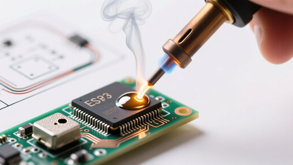
Transitioning from basic through-hole components to micro-SMD (Surface Mount Devices) fundamentally changes your approach to thermal management, metallurgy, and precision. Whether you are repairing a dense IoT motherboard or prototyping a wearable device, understanding how to solder electronics at the 0.4mm pitch level requires abandoning brute-force heat application in favor of controlled thermal profiles. In 2026, the miniaturization of consumer electronics means that 0402 and 0201 passive components, alongside Quad Flat No-lead (QFN) and Ball Grid Array (BGA) ICs, are the standard. This guide bypasses beginner tutorials and dives straight into the advanced metallurgical and mechanical techniques required for IPC Class 3 compliant assemblies.
The Advanced Workbench: Tooling and Metallurgy
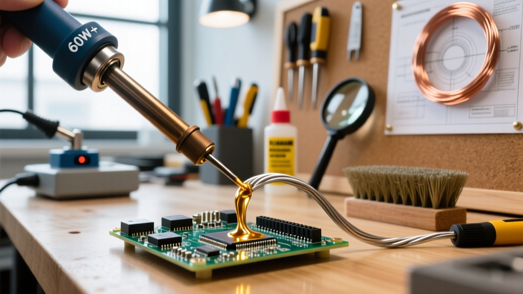
You cannot achieve micro-soldering precision with a generic $30 iron. Advanced rework demands rapid thermal recovery, specialized tip geometries, and optically magnified inspection. Below is the benchmark setup for a professional-grade advanced electronics soldering station.
| Equipment Category | Specific Model (2026 Standard) | Approx. Cost | Why It Matters |
|---|---|---|---|
| Soldering Station | JBC CD-2BQE with C245-945 Tip | $540 | Cartridge tips heat in 2 seconds; the micro-spoon tip holds a precise solder meniscus for drag soldering. |
| Hot Air Rework | Hakko FR-830 Preheater + 881D | $950 | Bottom preheating prevents board warping and reduces the thermal delta required from the top air gun. |
| Optics | AmScope 7X-45X Trinocular Boom | $380 | Essential for inspecting 0.5mm pitch leads and verifying solder fillet wetting angles. |
| Solder Paste | Chip Quik SMD4300AX10 (Type 4) | $35 | Type 4 powder (20-38µm) prevents bridging on fine-pitch stencils compared to standard Type 3. |
| Flux | Amtech NC-559-V2-TF No-Clean | $28 | High-tack, rosin-based flux that survives prolonged hot air exposure without burning off or splattering. |
The Chemistry of Flux and Solder Alloys
When working with micro-SMD, the choice between SAC305 (Lead-Free: Sn96.5/Ag3.0/Cu0.5) and Sn63Pb37 (Eutectic Lead) dictates your entire thermal strategy. Sn63Pb37 melts at a sharp 183°C, making it vastly superior for manual rework and drag soldering due to its lower thermal stress on adjacent components. SAC305 requires a liquidus temperature of 217°C–220°C, demanding higher iron temperatures (typically 360°C–380°C) and increasing the risk of delaminating PCB pads. Always use a high-activation no-clean flux like Amtech NC-559-V2-TF; its activators break down copper oxides at 180°C, ensuring capillary action pulls the solder under QFN pads before the alloy solidifies.
Technique 1: Drag Soldering Fine-Pitch TQFP/SOIC ICs
Drag soldering is the most efficient method for terminating 0.5mm pitch ICs (like the STM32F4 series or USB-C PD controllers). Instead of soldering 48 pins individually, you use a micro-spoon tip and surface tension to drag a molten bead of solder across the pins.
- Prep and Tack: Apply a thin layer of NC-559 flux to the PCB pads. Align the IC using vacuum pickup tweezers. Tack two diagonal corner pins with a standard conical tip to lock alignment.
- Flux Flood: Generously apply liquid flux over all pins. Do not skimp; the flux is what prevents the solder from bridging adjacent pins.
- Load the Tip: Using your JBC C245-945 micro-spoon, pick up a moderate bead of 0.015" Sn63Pb37 wire. The concave shape of the spoon holds the molten solder via capillary action.
- The Drag: Set the station to 340°C. Tilt the board slightly (about 15 degrees). Place the spoon tip at the top of the pin row and gently drag downward. Let gravity and the flux's surface tension pull the solder into the individual pad gaps.
- Wick the Excess: Inevitably, the last few pins will bridge. Apply fresh flux, place a 2.0mm desoldering wick (like Goot Wick CP-301) over the bridges, and press lightly with a clean chisel tip at 360°C for 1.5 seconds. The wick will absorb the excess, leaving perfect, separate fillets.
Technique 2: Hot Air Reflow for QFN Packages
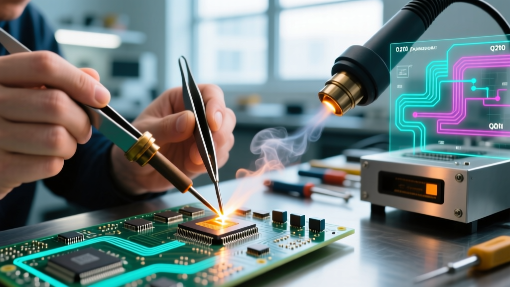
QFN packages hide their solder joints beneath the component, relying on a central thermal pad for grounding and heat dissipation. Hand-soldering these with an iron is impossible; you must use hot air reflow.
According to NASA's Workmanship Standards for surface mount assemblies, proper wetting on hidden thermal pads requires a controlled thermal profile that ensures the entire component reaches the solder's liquidus temperature simultaneously, preventing 'tombstoning' or voiding.
The Preheat Imperative
The most common failure mode in QFN reflow is the 'cold ground pad.' The massive copper pour on the PCB's inner layers acts as a heat sink, pulling thermal energy away from the center pad faster than the hot air can supply it. To combat this, you must use a bottom preheater (like the Hakko FR-830) to raise the ambient temperature of the entire PCB to 120°C–130°C. This reduces the thermal delta, allowing your top-air hot air gun (set to 350°C with 40% airflow) to push the component through the 217°C liquidus phase in roughly 30–45 seconds without scorching the FR4 fiberglass.
Troubleshooting Matrix: Edge Cases and Failure Modes
Even with premium tooling, advanced micro-soldering presents unique failure modes. Use this diagnostic matrix to troubleshoot your assemblies against IPC-A-610 Class 3 acceptance criteria.
| Defect | Root Cause Analysis | Advanced Corrective Action |
|---|---|---|
| Tombstoning (0402/0201) | Uneven wetting forces due to asymmetric pad heating or excessive solder paste volume on one pad. | Verify stencil aperture reduction (home-plate apertures). Ensure hot air nozzle is perfectly centered and perpendicular to avoid lateral wind force. |
| QFN Solder Voiding | Flux outgassing trapped under the thermal pad during the liquidus phase. | Switch to a low-voiding flux formulation. Introduce a 15-second 'soak' phase at 180°C before ramping to peak reflow temperature to allow solvents to evaporate. |
| Pad Cratering | Mechanical stress from prying a component off before the solder fully liquefies, or excessive iron dwell time. | Never use mechanical force. If a joint won't flow, add low-melting-point Bismuth solder (Sn42Bi58) to alloy with the existing SAC305, dropping the melt point to ~160°C for safe removal. |
| Solder Balling | Flux splattering due to rapid moisture expansion or applying hot air too close to the board. | Bake moisture-sensitive PCBs at 60°C for 4 hours prior to rework. Maintain a minimum 10mm standoff distance with the hot air nozzle. |
Maintaining Your Advanced Setup
At the micro-level, tip oxidation is your enemy. A layer of copper oxide acts as a thermal insulator, meaning your 360°C tip might only be transferring 240°C to the pad. Never leave your JBC or Hakko station at high temperatures while idle. Utilize the auto-sleep features (dropping to 150°C when the handpiece is holstered). Furthermore, clean your tips using a damp cellulose sponge or brass wool—never use abrasive files or sandpaper, which will strip the iron plating and destroy the tip's wetting capabilities. By respecting the metallurgy and adhering to strict thermal profiles, you elevate your electronics assembly from hobbyist guesswork to professional-grade engineering.