
[SCENE 1: WIDE SHOT] The Workshop Overview
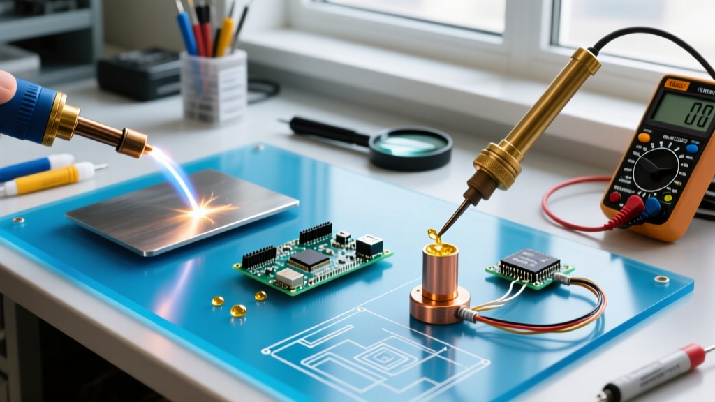
[Visual Cue: The camera pans across a fully equipped 2026 fabrication and electronics lab. On the left, a precision PCB rework station hums; in the center, an HVAC brazing rig sits ready; on the right, a TIG welding booth glows with a faint blue light.]
Understanding exactly what is the difference between welding soldering and brazing requires looking past the sparks and focusing on metallurgy. While all three processes utilize heat and filler metals to join materials, the defining metric is the liquidus temperature of the filler relative to the base metal's melting point. Whether you are assembling microcontrollers, repairing refrigeration linesets, or fabricating structural steel, choosing the wrong thermal process will result in catastrophic joint failure.
Director's Note: The fundamental dividing line is 840°F (450°C). Below this threshold, we are soldering. Above it, we are brazing. When the base metal itself melts, we cross into welding.
[SCENE 2: MACRO CLOSE-UP] Soldering & Capillary Action
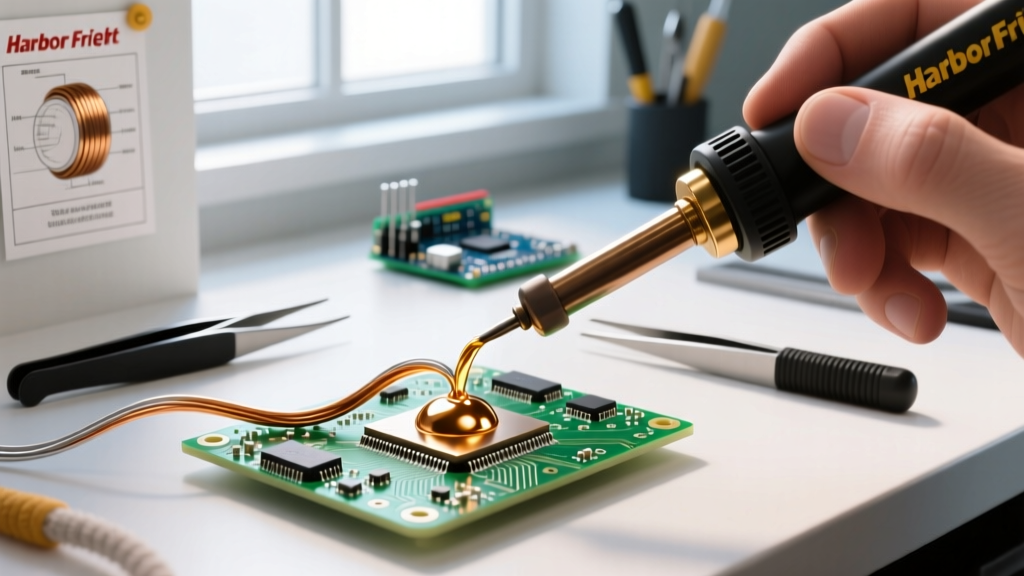
[Visual Cue: Extreme close-up of a Weller WES51 iron tip touching a copper through-hole pad. The flux core melts, bubbling slightly before the shiny liquid alloy flows into the barrel.]
Soldering operates at the lowest temperature threshold. The base metal never reaches its melting point; instead, the filler metal (solder) melts and wets the surface, relying entirely on capillary action and intermetallic compound (IMC) formation for adhesion.
The Alloys and Temperatures
- Sn63/Pb37 (Eutectic): Melts at exactly 361°F (183°C). Ideal for DIY electronics due to its sharp phase transition and glossy finish.
- SAC305 (Lead-Free): Composed of 96.5% Tin, 3% Silver, and 0.5% Copper. Melts at 423°F (217°C). Requires a higher iron tip temperature (typically 650°F to 700°F) and aggressive no-clean fluxes to overcome tin's natural oxidation.
In 2026, compliance with IPC-J-STD-001 requirements remains the gold standard for electronic assemblies. A proper solder joint requires heating the pad and the lead simultaneously for 1.5 to 3 seconds before applying the solder wire. Applying solder directly to the iron tip and dragging it to the joint is a critical error that causes flux burnout and cold joints.
[SCENE 3: THE TORCH PAN] Brazing & Metallurgical Bonding
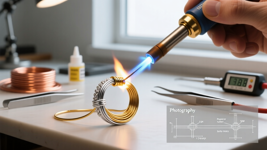
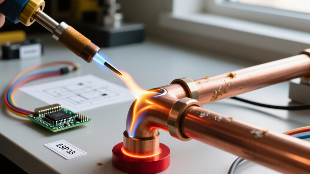
[Visual Cue: The lens shifts to a darkened HVAC workshop. A Harris 00680 oxy-acetylene torch heats a copper-to-steel joint. The copper glows a dull cherry red (~1100°F). The technician touches a silver-alloy rod, which instantly flashes into a liquid and disappears into the joint seam.]
Brazing is the heavy-duty cousin of soldering. Like soldering, the base metal does not melt. However, brazing occurs at temperatures above 840°F (450°C), resulting in significantly higher tensile strength. According to the Lucas-Milhaupt brazing fundamentals guide, a properly brazed joint can be stronger than the base metals themselves, often exceeding 60,000 PSI in shear strength.
Real-World HVAC Application
When joining copper refrigerant lines to a steel compressor valve, technicians use silver-bearing brazing alloys like Stay-Silv 15 (15% silver, melting range 1112°F–1270°F). Because copper oxidizes rapidly at these temperatures, a white brazing flux (like Stay-Silv White Flux) is mandatory to dissolve copper oxides and allow capillary flow. The joint clearance must be tightly controlled between 0.002 and 0.005 inches; if the gap is too wide, capillary action fails, and the joint will leak under high-pressure R-410A or R-32 refrigerant cycles.
[SCENE 4: HIGH-HEAT WIDE ANGLE] Welding & Fusion
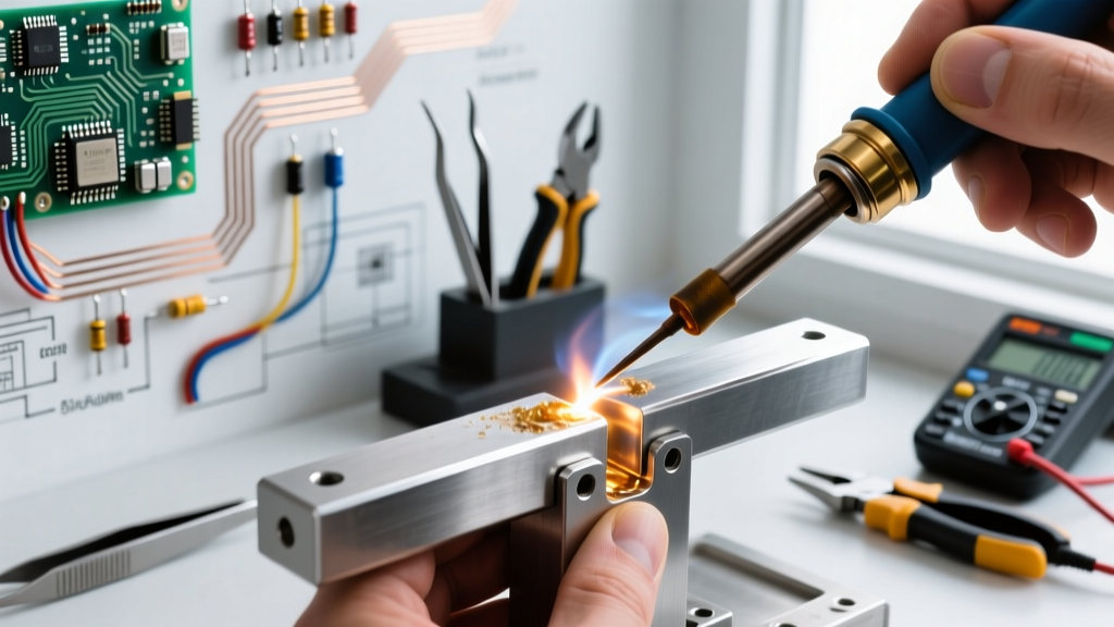
[Visual Cue: Auto-darkening welding helmet snaps down. A Miller Dynasty 210 TIG torch initiates a high-frequency arc on 1/8-inch carbon steel. The tungsten electrode hovers as a molten puddle forms, blending the base metal and the ER70S-2 filler rod into a single homogeneous mass.]
Welding is the only process where the base metals are melted and fused together. The filler metal (if used) acts as a reinforcement or bridge, but the structural integrity comes from the fusion zone—the area where the crystalline structures of the two base pieces interlock as they cool.
The Heat-Affected Zone (HAZ)
Because welding requires temperatures exceeding 2,500°F for steel, it creates a Heat-Affected Zone (HAZ) bordering the weld puddle. In high-carbon steels, rapid cooling can cause martensitic transformation, making the HAZ brittle and prone to cracking. This is why pre-heating and post-weld heat treatment (PWHT) are mandated by American Welding Society (AWS) structural codes for critical load-bearing joints.
[SPLIT SCREEN] The Master Comparison Matrix
[Visual Cue: A digital overlay appears on screen, freezing the three workshop stations side-by-side with a data matrix.]
| Process | Temp Threshold | Base Metal State | Filler Metal | Typical Tensile Strength | Primary Use Case |
|---|---|---|---|---|---|
| Soldering | < 840°F (450°C) | Solid | Tin/Lead or SAC | 2,000 - 6,000 PSI | Electronics, PCB, low-stress plumbing |
| Brazing | > 840°F (450°C) | Solid | Silver, Brass, Copper-Phos | 40,000 - 70,000+ PSI | HVAC, bicycle frames, carbide tooling |
| Welding | > 2,500°F (1370°C) | Liquid (Melted) | Steel, Aluminum, Inconel | Matches Base Metal | Structural steel, automotive, aerospace |
[SCENE 5: X-RAY OVERLAY] Failure Modes & Edge Cases
[Visual Cue: The screen transitions to an X-ray and macro-lens view, highlighting microscopic defects in poorly executed joints.]
Soldering: The Disturbed Cold Joint
If a component lead is moved while the SAC305 solder is transitioning from liquid to solid (the plastic phase), the crystalline structure fractures. Visually, the joint looks dull, grainy, and bulbous rather than smooth and concave. Electrically, this creates a high-resistance connection that will fail under thermal cycling.
Brazing: Flux Inclusions
A common edge case in silver brazing is trapping unburnt flux inside the capillary gap. If the technician heats the joint unevenly or uses excessive flux, the flux turns into a glassy slag that blocks the filler metal. The joint looks perfect on the outside but will fail catastrophically under vibration or pressure testing.
Welding: Porosity & Lack of Fusion
Porosity appears as tiny gas bubbles trapped in the weld bead, resembling a sponge on an X-ray. This is almost always caused by inadequate shielding gas coverage. For TIG welding aluminum with a Miller Dynasty 210, an Argon flow rate below 15 CFH (Cubic Feet per Hour) or a draft in the welding booth will strip the shielding envelope, allowing atmospheric nitrogen and oxygen to contaminate the molten puddle.
[FINAL CUT] Decision Framework
When engineering a joint, use this rapid decision tree:
- Are you joining electrical components or heat-sensitive microchips? Use Soldering (SAC305 or Sn63/Pb37). Keep peak temperatures below 450°F to prevent delaminating the PCB substrate.
- Are you joining dissimilar metals (e.g., copper to steel) or need a leak-proof pressure joint without warping the base metal? Use Brazing (Silver or Copper-Phosphorus alloys). The lower heat input prevents the thermal distortion associated with welding.
- Do you need maximum structural load-bearing capacity for heavy machinery or structural frames? Use Welding (TIG/MIG/Stick). Ensure proper edge preparation (beveling) and shielding gas flow rates to guarantee full penetration.
[FADE TO BLACK. Electrical Flux Logo appears with the tagline: 'Master the Melt.']