
The Thermodynamics of Vacuum Desoldering on High-Tg Boards
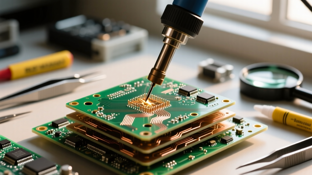
Most introductory guides on how to use a desolder pump focus on single-layer, through-hole hobby boards. However, when you transition to multi-layer printed circuit boards (PCBs) featuring internal ground planes and high glass transition temperature (Tg) laminates, basic techniques lead to catastrophic failure modes like pad lifting, via barrel tearing, and internal delamination. Modern 4-to-8-layer boards act as massive thermal heat sinks. The internal copper planes rapidly wick heat away from the plated through-hole (PTH) barrel, meaning the surface solder might melt while the core of the via remains solid.
To execute advanced rework, you must understand the thermal limits of your substrate. Standard FR-4 material has a Tg (glass transition temperature) of around 130°C to 140°C, while high-Tg polyimide or advanced FR-4 can withstand 170°C+. If you apply a 400°C iron to a via for more than 3 to 4 seconds attempting to clear a stubborn ground pin, you risk exceeding the laminate's decomposition temperature (Td), causing the resin to vaporize and the copper annular ring to detach from the fiberglass weave. According to the NASA-STD-8739.3 Workmanship Manual, controlled thermal profiling and strict dwell-time limits are mandatory for high-reliability aerospace assemblies to prevent these exact micro-fractures.
Metallurgical Hacking: The Eutectic Pre-Tinning Method
Factory-assembled modern electronics predominantly use lead-free SAC305 (Tin-Silver-Copper) solder, which has a liquidus temperature of 217°C to 220°C. This high melting point requires aggressive heat application, increasing the risk of thermal damage to surrounding surface-mount components and the PCB substrate. Before you even think about engaging your vacuum tool, you must alter the metallurgy of the joint.
Lowering the Liquidus Threshold
By flooding the existing lead-free joint with high-quality 63/37 (Sn63Pb37) eutectic leaded solder, you create a mixed-alloy transitional joint. This dramatically lowers the effective melting point of the via's solder mass closer to 183°C. This technique allows you to use a lower iron temperature (typically 340°C to 360°C instead of 390°C+), preserving the integrity of the PTH barrel and the surrounding copper traces while ensuring the entire depth of the via reaches a fully molten state simultaneously.
Step-by-Step: How to Use a Desolder Pump for Via Preservation
Understanding exactly how to use a desolder pump in a high-reliability context requires a departure from the standard 'heat and suck' methodology. Follow this advanced protocol to ensure complete solder evacuation without mechanical stress to the board.
- Flux Saturation: Apply a high-tack, no-clean flux gel (such as Amtech NC-559) directly into the via and around the component lead. Flux is not just for cleaning; it acts as a vital thermal transfer medium, bridging the microscopic air gaps between the iron tip, the lead, and the solder.
- Thermal Bridging: Use a hollow desoldering tip matched precisely to the diameter of the pad. If the tip is too small, it will only heat the surface. If it is too large, it will transfer excess heat to adjacent traces. Allow the iron to dwell on the joint for 1.5 to 2 seconds before introducing fresh eutectic solder to establish a thermal bridge.
- The Molten Verification: Watch the solder pool closely. You are looking for capillary action—the moment the solder visibly wicks down into the barrel and flashes on the opposite side of the board (if accessible), the entire thermal mass is molten.
- Orthogonal Vacuum Engagement: This is where most technicians fail. The nozzle of the desolder pump must be applied at a strict 90-degree angle to the board surface. Applying lateral pressure while the vacuum engages will physically rip the softened copper pad off the substrate. Press down firmly to create an airtight seal, then trigger the pump.
- The 'Pop' Release: Do not pull the iron and the pump away simultaneously. Trigger the pump, wait 0.5 seconds for the vacuum to pull the molten solder into the PTFE chamber, and then lift the pump straight up. Leave the iron on the joint for one additional second to allow the remaining microscopic solder film to cool naturally, preventing thermal shock to the via barrel.
Expert Insight: Never use a desolder pump to 'chase' cold solder. If the pump triggers and the solder remains in the via, the joint was not fully molten. Re-apply flux, add more eutectic solder to increase the thermal mass, and try again. Repeatedly triggering a cold pump will destroy your tool's internal O-ring and scratch the PTH barrel.
Tool Anatomy: Maintaining the PTFE Nozzle and Vacuum Seal
High-end electric desoldering tools, like the Hakko FR-301 or the Engineered SS-360S, rely on precision-machined internal components to generate the necessary negative pressure (often exceeding 500 mmHg). Over time, vaporized flux resin and microscopic solder splatter accumulate inside the heating chamber, degrading performance.
Preventative Maintenance Protocol
- PTFE Tip Replacement: The Teflon (PTFE) nozzle that contacts the PCB is a consumable. Once the tip becomes charred or the aperture widens by even 0.2mm, it will fail to create a localized vacuum seal, resulting in splattered solder balls across your board. Replace these tips every 40-50 hours of active use.
- Ceramic Filter Cleaning: Behind the heating element lies a ceramic paper filter designed to catch flux vapor before it reaches the vacuum diaphragm. If this filter becomes saturated with carbonized flux, the pump's airflow drops drastically. Inspect and replace this filter weekly in heavy rework environments.
- O-Ring Lubrication: The primary vacuum seal relies on a high-temperature silicone O-ring. Never use petroleum-based greases, which will cause the silicone to swell and fail. Use only pure dielectric silicone grease to maintain pliability and seal integrity.
Troubleshooting Vacuum Loss and Solder Splatter
When mastering how to use a desolder pump on complex assemblies, you will inevitably encounter mechanical or thermal failures. Use this diagnostic matrix to identify and resolve issues without damaging the PCB.
| Failure Mode | Root Cause Analysis | Advanced Solution |
|---|---|---|
| Solder 'Blowback' (Splatter) | Vacuum triggered before solder was fully molten, or air leak in the PTFE nozzle seal. | Increase iron wattage/dwell time; ensure nozzle is perfectly flush and orthogonal to the pad. |
| Partial Via Clearing | Internal ground planes wicked heat away; lower layers remained solid while surface melted. | Pre-tin with 63/37 eutectic; use a board pre-heater (set to 100°C) to reduce the thermal delta. |
| Weak Vacuum Suction | Saturated ceramic filter or degraded internal diaphragm O-ring. | Disassemble the tool; replace the ceramic filter and apply high-temp silicone grease to the O-ring. |
| Annular Ring Lifting | Lateral mechanical force applied during vacuum trigger; substrate Tg exceeded. | Strictly enforce 90-degree vertical pump alignment; lower iron temperature and use eutectic mixing. |
Advanced Hybrid Technique: Pump and Braid for BGA Pads
While desolder pumps are unparalleled for clearing through-hole vias, they are entirely unsuited for surface-mount pads, particularly the dense array of pads left behind after removing a Ball Grid Array (BGA) component. Attempting to use a vacuum pump on flat SMD pads will result in severe track tearing.
For these scenarios, the industry standard—documented extensively in the IPC-7711/7721C Rework Standard—dictates a hybrid approach. Use the desolder pump to remove the bulk of the solder from any associated grounding vias or large thermal relief pads. Then, transition to high-purity, oxygen-free copper desoldering braid (wick) coated in rosin flux to flatten the remaining SMD pads. The braid utilizes capillary action to draw the microscopic residual solder away without applying any vertical mechanical stress to the delicate surface traces.
Ultimately, knowing how to use a desolder pump at an expert level is less about the physical act of pulling a trigger and more about mastering the thermodynamics of the PCB, the metallurgy of the solder alloys, and the precise maintenance of your vacuum equipment. By respecting the thermal limits of your substrates and maintaining your tool's internal seals, you can execute flawless, high-yield rework on even the most complex multi-layer architectures.