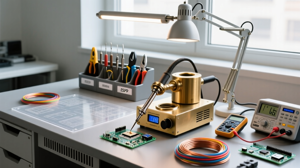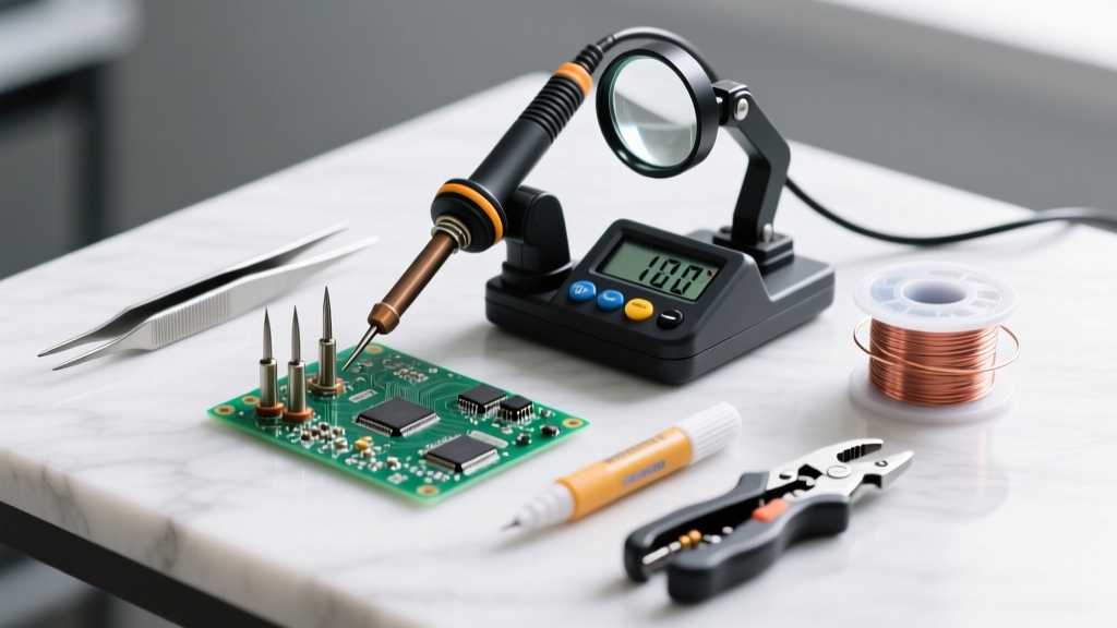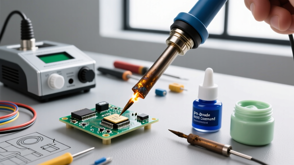

Introduction: The Weller Standard in Professional Electronics
When you invest in a Weller soldering kit, you are purchasing decades of thermal engineering. Whether you are deploying the legendary analog WES51 (often sourced for $120-$150 on the surplus market in 2026) or the modern digital WE1010NA (MSRP $389), out-of-the-box performance relies entirely on proper initial setup. Many hobbyists and junior technicians plug their stations in and immediately burn their first tip through oxidation or crack the ceramic heater core through mechanical over-torquing. This comprehensive tutorial bridges the gap between unboxing and professional IPC-compliant soldering, detailing exact calibration procedures, thermal profiling, and ESD bench integration.
Unboxing and Component Verification
Before applying power, verify that your kit contains the correct matched components. Mismatched heating elements and sensors are a primary cause of early Weller station failure.
- For the WES51 (Analog): Verify the presence of the PES51 soldering pencil, the PH50 heating element (ceramic core with integrated sensor), and the ETA chisel tip. Ensure the 4-pin DIN connector pins are perfectly straight.
- For the WE1010NA (Digital): Confirm the WSP80 iron, the XH40 heating element, and the RT series micro-tip. The digital station utilizes a proprietary multi-pin connector; inspect the silicone cable for any shipping kinks that might compromise internal thermocouple wires.
Expert Warning: Never attempt to bend the pins on a Weller iron connector. A misaligned pin will short the 24V AC heater supply directly into the low-voltage thermocouple sensor circuit, instantly destroying the station's internal TRIAC or microcontroller.
Physical Assembly: Avoiding the Ceramic Heater Killer
The most common catastrophic failure during Weller kit setup is cracking the ceramic heater core. The heating element is a fragile cylinder that slides into the metal wand. Follow this exact sequence to secure it:
- Insert the Element: Gently slide the PH50 or XH40 heater into the stainless steel barrel of the iron. It should slide in with zero resistance. If it catches, stop immediately and realign.
- Seat the Tip: Slide the copper tip over the heater element. Ensure the internal notch of the tip aligns with the ceramic sensor bump on the element.
- Thread the Locking Nut: Hand-thread the stainless steel locking nut onto the wand. Do not use pliers or a wrench.
- The 1/8-Turn Rule: Once hand-tight, use the included Weller wrench (or your fingers) to tighten the nut exactly 1/8th of a turn past finger-tight. Overtightening compresses the ceramic core against the steel barrel, causing microscopic fractures that expand when the element reaches 350°C, leading to an open-circuit failure.
Thermal Calibration: Analog vs. Digital Stations
Factory calibration is performed at sea level under specific ambient conditions. To meet IPC J-STD-001 requirements for thermal accuracy, you must verify and adjust your station's output using a K-type thermocouple and a calibrated digital multimeter (DMM).
Calibrating the Analog WES51
The WES51 uses a magnetic Curie-point-inspired analog control loop, but it features an internal trim potentiometer for baseline offset calibration.
- Set the front dial to '7' (the factory baseline for approximately 350°C / 662°F).
- Allow the station to heat for 5 minutes until the red LED indicator begins to cycle slowly.
- Clamp the K-type thermocouple bead directly to the flat working face of the ETA tip using a high-temperature silicone tweezer.
- Apply a drop of liquid flux to the thermocouple junction to ensure thermal transfer.
- Open the bottom plate of the WES51 base. Locate the small brass trim pot labeled 'CAL'.
- Using a ceramic flathead jeweler's screwdriver, adjust the pot until your DMM reads exactly 350°C. Turn clockwise to increase, counter-clockwise to decrease. Make adjustments in 1mm increments and wait 15 seconds for thermal stabilization between turns.
Calibrating the Digital WE1010NA
The WE1010NA simplifies this process via its digital menu interface, eliminating the need to open the chassis.
- Press and hold both the UP and DOWN arrows for 3 seconds to enter the configuration menu.
- Navigate to the 'CAL' (Calibration) submenu.
- Measure the tip temperature with your thermocouple setup as described above.
- Use the arrows to input the exact temperature offset (e.g., if the display reads 350°C but your DMM reads 342°C, input an offset of +8°C).
- Press the center dial to save. The station will reboot and apply the new thermal mapping.
Tip Selection and Thermal Profiling Matrix
Selecting the correct tip geometry and mass is critical for thermal recovery. In 2026, the industry standard for consumer electronics is SAC305 (96.5% Sn, 3.0% Ag, 0.5% Cu) lead-free alloy, which requires higher thermal mass than legacy 63/37 tin-lead. Below is the recommended Weller thermal profiling matrix:
| Weller Tip Series | Geometry / Mass | Target Application | Optimal Temp (SAC305) | Optimal Temp (63/37 SnPb) |
|---|---|---|---|---|
| ET Series (ETA) | Standard Chisel / Medium | Through-hole, 0805 SMD, general wiring | 360°C (680°F) | 315°C (600°F) |
| RT Series (RTW) | Micro Pico / Low Mass | 0402/0201 SMD, dense PCB repair | 340°C (645°F) | 300°C (570°F) |
| LT Series (LTA) | Heavy Chisel / High Mass | Ground planes, large gauge wire, XT60 | 380°C (715°F) | 340°C (645°F) |
The First Tin: Priming for Longevity
The moment your Weller station reaches temperature, the bare iron plating on the tip begins to oxidize. You have a window of approximately 15 seconds before irreversible micro-pitting occurs. Follow this priming protocol:
- Use the Right Alloy: For the initial tinning, always use a heavily fluxed 63/37 rosin-core wire (such as Kester 44 or Alpha Metals), even if you plan to solder with lead-free SAC305 later. The 63/37 alloy wets faster at lower temperatures, providing an immediate protective barrier.
- Flood the Working Face: Melt a generous 5mm bead of solder directly onto the working surface of the tip. Do not wipe it off immediately.
- Cool and Wipe: Turn the station off and let the tip cool to room temperature with the solder bead intact. Once cool, turn it back on, and the moment it melts, wipe it on a damp (not soaking) cellulose sponge or brass wire wool. Re-apply a fresh, thin coat of solder before putting the iron in the holder.
ESD Grounding and Bench Integration
Weller stations are designed with integrated ESD (Electrostatic Discharge) safety, but this is useless if your bench is not properly configured. According to the EOS/ESD Association, a grounded operator and workstation are mandatory when handling MOSFETs, CMOS ICs, and raw microcontrollers.
Your Weller WES51 or WE1010NA features a dedicated 4mm banana jack on the rear panel. This jack is tied directly to the earth ground of the station's 3-prong power cord. To complete the circuit:
- Connect a 1-megohm grounding cord from your ESD dissipative mat to the station's banana jack.
- Connect your wrist strap to a secondary 1-megohm cord, which can be daisy-chained to the same mat or a dedicated earth ground bus bar.
- Verify the resistance from the tip of the soldering iron to your wrist strap using a multimeter. It should read between 1 and 10 megohms, ensuring safe dissipation of static charges without creating a dangerous shock hazard if you touch a live AC circuit.
Troubleshooting Common Setup Faults
Even with meticulous setup, environmental factors or manufacturing variances can trigger faults. Here is how to diagnose the most common initial errors:
Flashing Red LED on WES51 (Sensor Failure)
If the WES51 LED flashes rapidly and the iron fails to heat, the control board has detected an open or shorted thermocouple. Fix: Unplug the iron. Inspect the 4-pin DIN connector. If the pins are clean, the internal sensor wire inside the PH50 heater has likely snapped. The PH50 is a replaceable consumable (approx. $35); swap it out and recalibrate.
H3 Error Code on WE1010NA
The H3 code indicates a thermocouple short circuit or a temperature reading exceeding 480°C. Fix: This is almost always caused by solder wicking down the tip and bridging the gap between the heater core and the sensor wire at the base of the wand. Remove the tip, clean the base of the heater element with isopropyl alcohol and a fiberglass scratch pen, and ensure you are not over-tinning past the shoulder of the tip.
Conclusion
A Weller soldering kit is a precision thermal instrument. By taking the extra twenty minutes to properly torque the locking nut, calibrate the internal offsets against a trusted thermocouple, and integrate the station into your ESD bench matrix, you guarantee IPC-compliant joints and extend the lifespan of your tips and heating elements by years. For further reading on professional soldering standards, refer to the latest guidelines published by Weller Tools and the IPC.