
The Metallurgy of Replacement Soldering Tips
In the 2026 landscape of electronics assembly and micro-SMD rework, treating replacement soldering tips as mere consumable accessories is a critical error. A soldering tip is the primary thermal transfer tool in your arsenal. Understanding its metallurgy is the first step in a proper tool-by-tool assessment. Modern high-quality tips are not solid copper; they are complex, multi-layered composite tools. The core is typically oxygen-free copper (thermal conductivity of approximately 400 W/m·K) for rapid heat transfer. This core is electroplated with a 100 to 150-micron layer of iron. This iron plating is the actual working surface—it prevents the molten solder from dissolving the copper core. Over the iron, a microscopic layer of chromium is applied to the non-wetting areas to prevent solder creep, while the working end is tinned with a protective layer of pure tin or tin-lead alloy to prevent oxidation during storage.
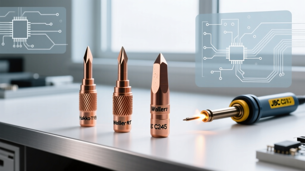
When sourcing replacement soldering tips, you are essentially choosing between three dominant thermal architectures. Below, we assess these ecosystems tool-by-tool, evaluating their specific geometries, thermal recovery profiles, and inherent failure modes.
Tool-by-Tool Ecosystem Assessment
1. Hakko T18 Series: The Convection Workhorse
The Hakko T18 series remains the undisputed standard for general-purpose through-hole and large SMD (0805 and above) soldering. In this ecosystem, the heating element and sensor reside in the soldering iron handle, and the replacement tip slides over the ceramic heater as a hollow sleeve.
- Assessed Models: T18-D24 (2.4mm Chisel) and T18-B (Standard Conical).
- Cost Profile: $7.00 to $9.50 per replacement tip.
- Thermal Dynamics: Because the sensor is in the handle, there is inherent thermal lag. When a large ground plane draws heat away from the T18-D24, the handle sensor takes 3 to 5 seconds to detect the temperature drop and command the heater to compensate.
- Edge Case Warning: Never use the T18-B (conical) for heavy ground planes. The minimal surface area results in poor thermal transfer, leading to prolonged dwell times that can delaminate PCB pads.
2. Weller RT Series: Active-Heating Precision
For micro-soldering, 0201 components, and micro-BGA rework, the Weller RT series represents a paradigm shift. These are not just tips; they are active heating cartridges where the heater, sensor, and tip geometry are a single, integrated unit.
- Assessed Models: RTW2 (Pico, 0.2mm tip) and RT1 (1.0mm Chisel).
- Cost Profile: $40.00 to $45.00 per cartridge.
- Thermal Dynamics: Zero thermal lag. The sensor is located fractions of a millimeter from the working edge, allowing the station to pulse power instantaneously. This is critical for preventing thermal shock to sensitive silicon dies.
- Failure Mode: Mechanical fragility. The internal ceramic heater element is highly susceptible to snapping if lateral pressure is applied during rework. These tools must be used with a feather-light touch, relying on capillary action rather than physical force.
3. JBC C245 Cartridges: The Professional Benchmark
JBC’s C245 system is the gold standard for high-volume production and advanced rework stations. Like the Weller RT, it is an integrated cartridge, but it features a proprietary collet system that delivers unmatched thermal recovery.
- Assessed Models: C245-903 (Chipblade 1.3x0.3mm) and C245-112 (Conical Bent).
- Cost Profile: $55.00 to $65.00 per cartridge.
- Thermal Dynamics: The C245-903 can recover from a 50°C temperature drop back to 350°C in under 2 seconds. This allows technicians to drag-solder multi-pin ICs without pausing between pins.
- Edge Case Warning: Carbon buildup in the handle collet. Because the C245 relies on high-current, low-voltage electrical contacts at the base of the cartridge, vaporized flux can create an insulating carbon layer in the handle. If not cleaned monthly with isopropyl alcohol and a cotton swab, the station will exhibit erratic temperature swings and throw sensor errors.
Tip Geometry Matrix: Matching Shape to Joint
Selecting the correct replacement soldering tip geometry is just as critical as the thermal architecture. The wrong shape compromises the meniscus formation required for a reliable metallurgical bond. According to the NASA Workmanship Training Manual for Soldering, proper wetting requires the solder to flow smoothly and form a concave fillet, which is heavily dependent on tip geometry and surface tension.
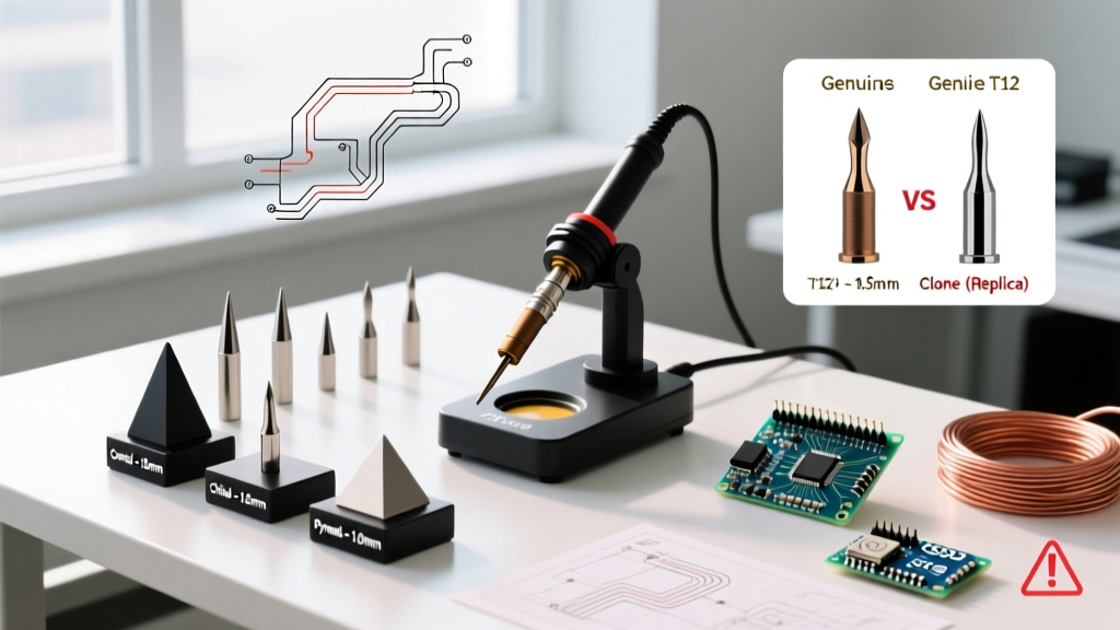
| Geometry | Ideal Application | Wetting Surface Area | Edge Case Warning |
|---|---|---|---|
| Chisel (D-Series) | Through-hole leads, 0805 SMD, general wiring | High (Flat face maximizes thermal transfer) | Can bridge fine-pitch IC pins if width exceeds pad spacing. |
| Bevel / Hoof (C-Series) | Drag soldering, large ground planes, wire tinning | Very High (Concave shape holds molten solder) | Prone to trapping flux residue in the hollow; requires aggressive cleaning. |
| Conical (B-Series) | Micro-SMD (0402), tight-pitch jumper wires | Low (Point contact only) | Worst thermal transfer. Avoid for anything requiring >15W of continuous heat. |
| Knife (K-Series) | Plunge soldering, cleaning tight corners, SOIC pins | Variable (Use the edge for precision, flat for heat) | The sharp point degrades rapidly if used to pry components off the board. |
Flux Chemistry and Plating Degradation
The lifespan of your replacement soldering tips is inextricably linked to the chemistry of the flux you use. In 2026, the market is flooded with highly active no-clean (NC) and water-soluble (WS) fluxes designed for lead-free SAC305 alloys, which require higher processing temperatures (340°C to 380°C).
When activated at these elevated temperatures, the organic acids (such as adipic or succinic acid) in the flux become highly corrosive. If left on the iron plating, these acids will micro-etch the iron layer. Once the iron plating is breached, the underlying copper core is exposed to the molten solder. Copper dissolves into tin-based solder at an alarming rate—a phenomenon known as leaching. A tip that suffers copper leaching will develop deep craters and pits, rendering it useless in a matter of hours. The IPC J-STD-001 standard heavily emphasizes the control of flux residues and thermal profiles to prevent exactly this type of metallurgical degradation in both the joint and the tooling.
Diagnostic Guide: Real-World Failure Modes
Before discarding a tip, diagnose the failure mode to prevent repeating the mistake with your next replacement.
- Black Tip Syndrome (Oxidation): The working end turns dark grey or black and solder rolls off in balls. Cause: Leaving the iron on at >350°C without a protective blob of solder, or using dry sponges. Fix: Use a brass wire sponge and a specialized tip tinner (e.g., Hakko 599B). Never use sandpaper or files, which will instantly destroy the iron plating.
- Pitting and Cratering: Visible divots or rough, sandy textures on the working surface. Cause: Flux corrosion eating through the iron plating to the copper core, or using highly acidic plumbing fluxes on electronics. Fix: The tip is dead. Switch to a lower-activity rosin-based (RO) flux for manual soldering.
- De-wetting on Non-Working Surfaces: Solder creeping up the sides of the tip. Cause: The microscopic chromium barrier layer has been scratched or compromised, often by tapping the tip against the soldering station stand to knock off excess solder. Fix: Stop tapping. Use the brass sponge to gently wipe the tip.
Actionable Maintenance Protocol for Maximum Lifespan
To maximize the ROI on premium replacement soldering tips, implement this strict shutdown and maintenance protocol in your workspace:
- The Pre-Shutdown Tinning: Never turn off your station with a clean tip. Before powering down, apply a massive, generous blob of 63/37 rosin-core solder to the working end. This sacrificial layer will oxidize instead of your iron plating while the tip cools.
- Temperature Discipline: Do not use 400°C as a default 'fast heating' setting. For standard 63/37 SnPb solder, 320°C to 340°C is optimal. For SAC305 lead-free, 350°C to 360°C is sufficient. Every 10°C increase above necessary halves the lifespan of the iron plating.
- Proper Wiping Technique: If using a cellulose sponge, ensure it is dampened with distilled water, not tap water. Tap water contains minerals and chlorides that accelerate galvanic corrosion on the hot iron plating. The sponge should spring back when squeezed, not drip water.
- Collet Maintenance: For integrated cartridge systems (JBC/Weller), remove the cartridge weekly and wipe the internal contacts of the handle with a lint-free swab and 99% isopropyl alcohol to ensure optimal electrical conductivity.
Expert Insight: A soldering tip is a thermal bridge, not a mechanical pry bar. Applying downward pressure to force heat into a joint is the hallmark of an amateur. If the joint isn't melting, your tip geometry is wrong, your thermal mass is insufficient, or your flux has failed. Increase the surface area of the tip, not the pressure of your hand.
By assessing your replacement soldering tips not just by their shape, but by their thermal architecture and metallurgical limits, you transition from simply replacing worn-out parts to actively engineering your soldering process for reliability and speed.