
Building a Professional Workspace Around Your Iron Soldering Kit
Upgrading to a high-quality iron soldering kit is only the first step toward electronics mastery. The environment in which you operate dictates your joint quality, component survival rate, and long-term respiratory health. In 2026, with surface-mount components shrinking to 0201 and 01005 imperial sizes, and lead-free alloys demanding higher thermal profiles, a haphazard kitchen-table setup is a recipe for damaged PCBs and cold joints. This comprehensive workspace setup guide will walk you through the exact specifications, environmental controls, and ergonomic adjustments required to build a professional-grade bench tailored specifically to your iron soldering kit.
⚠️ Critical Safety Warning: Never solder in an unventilated room. Rosin-based flux fumes (colophony) are a known respiratory sensitizer and can cause occupational asthma. Always pair your iron soldering kit with active fume extraction.Selecting the Core Iron Soldering Kit for Bench Integration
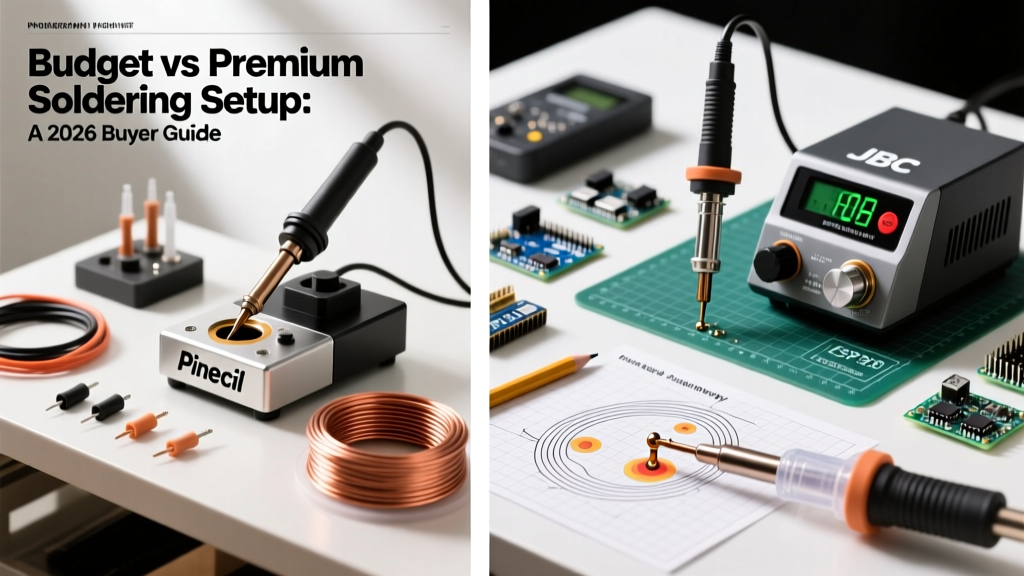
Before routing power and laying down mats, we must define the thermal engine of your workspace. The market in 2026 is split between traditional transformer-based stations, high-frequency induction systems, and modern USB-C PD (Power Delivery) smart irons. Your choice dictates your bench's power requirements and physical footprint.
| Kit Model | Temp Stability | Tip Ecosystem | 2026 Street Price | Best Workspace Use |
|---|---|---|---|---|
| Pinecil V2 (PD 3.1) | ±2°C | TS100 / T12 | $26 (bare) / $45 (kit) | Compact desks, field repair |
| Hakko FX-888D | ±1°C | T18 | $115 - $130 | Daily benchwork, education |
| Weller WE1010NA | ±1°C | ET / XT | $120 - $140 | Heavy ground planes, lead-free |
| JBC CD-2BQE | ±0.5°C | C245 / C210 | $350 - $400 | Micro-SMD, 01005 components |
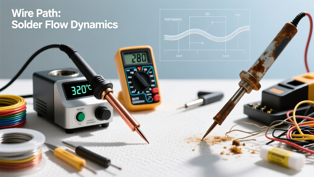
Expert Insight: If your iron soldering kit relies on standard T12 or T18 tips, remember that these tips feature a copper core plated with roughly 150 to 200 microns of iron. Never file modern tips or use abrasive sponges; doing so breaches the iron plating, allowing the molten solder to dissolve the copper core and destroying the tip in hours. Always use a brass wire sponge (like the Hakko 599B) and tip tinner for maintenance.
Environmental Controls: Ventilation and Airflow
Soldering generates particulate matter and volatile organic compounds (VOCs). According to Cornell University Environmental Health and Safety, localized exhaust ventilation (LEV) is mandatory for capturing colophony and flux vapors before they enter your breathing zone. A standard desk fan merely blows these sensitizers across the room, contaminating other surfaces and failing to protect your lungs.
Fume Extractor Specifications
- Airflow Rate: Look for a minimum of 70 CFM (Cubic Feet per Minute) for a single-user bench.
- Filtration Stages: You need a dual-stage system. A HEPA filter captures fine particulate matter (down to 0.3 microns), while an activated carbon bed (minimum 2 lbs of carbon) adsorbs the VOCs and rosin fumes.
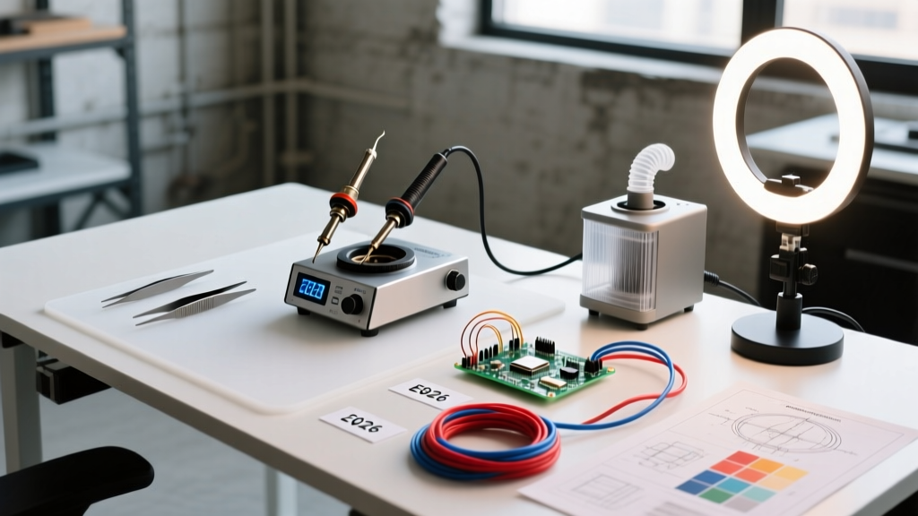
- Placement: The extraction hood must be positioned 6 to 8 inches from the solder joint, directly in the path of the thermal plume rising from your iron soldering kit. Do not place it across your body, or you will pull fumes directly through your breathing zone.
ESD Protection and Surface Preparation
Static electricity is the silent killer of modern MOSFETs and microcontrollers. Human body model (HBM) discharges can easily exceed 3,000 volts in a dry, climate-controlled room—far above the 100-volt threshold that damages sensitive IC gates. To protect your projects, your workspace must comply with the principles outlined by the ESD Association Standards, specifically ANSI/ESD S20.20.
The Anatomy of an ESD-Safe Bench Mat
Do not rely on cheap, pure-silicone 'repair mats' sold on generic marketplaces if you are handling bare ICs. While silicone is heat-resistant up to 500°C, it is an insulator and will hold a static charge. Instead, invest in a dissipative rubber mat, such as the Desco 23100 series.
- Surface Resistance: Must measure between $1.0 \times 10^6$ and $1.0 \times 10^9$ ohms. This allows static charges to bleed off slowly and safely, preventing a destructive rapid discharge.
- Grounding: The mat must be connected to a verified earth ground via a 10mm snap and a grounding cord containing a built-in 1-megohm safety resistor. This resistor protects you from lethal shock if you accidentally touch a live AC mains voltage while grounded.
- Wrist Strap Integration: Your body must be at the same electrical potential as the mat and the PCB. Wear an adjustable ESD wrist strap connected to the same common point ground as your mat.
"The most common failure mode in DIY electronics isn't bad solder; it's latent ESD damage. A component might survive the initial zap but fail weeks later in the field due to metallization degradation. Treat your iron soldering kit workspace as a controlled EPA (ESD Protected Area)." — Senior Reliability Engineer, IPC Certified.
Lighting and Optical Magnification
As component pitches shrink to 0.4mm and 0.3mm (common in modern QFN and BGA packages), standard overhead room lighting (usually 300 lux) is woefully inadequate. The IPC-A-610 standard for electronic assembly acceptability requires high-intensity, shadow-free lighting for inspection and rework.
Illumination Targets
Aim for 500 to 1,000 lux directly at the work surface. Use an articulating LED desk lamp with a high CRI (Color Rendering Index > 90). A high CRI ensures you can accurately distinguish between a dull, oxidized cold joint and a shiny, healthy eutectic fillet. Ring lights mounted directly around your magnification optics are ideal for eliminating shadows cast by your hands and the iron itself.
Magnification Solutions
For through-hole and large SMD work, a traditional helping-hands rig with a 3x to 5x magnifying glass suffices. However, for precision SMD rework using a micro-pencil tip on your iron soldering kit, an articulating boom stand microscope (like the AmScope SE400-Z or a digital HDMI microscope) is mandatory. Digital microscopes introduce slight latency, which can make drag-soldering difficult; optical stereo microscopes remain the gold standard for real-time hand-eye coordination.
Ergonomics: Board Holding and Cable Routing
A cluttered bench leads to burnt cables and knocked-over flux bottles. Proper cable management and board fixation are critical for workflow efficiency.
Third-Hand Solutions
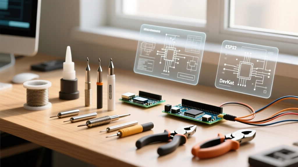
Stop using cheap, alligator-clip 'helping hands' that scratch your PCBs and fail to hold heavy boards flat. Upgrade to a dedicated PCB vise. The PanaVise 204 or the QuadHands Workbench allow you to tilt and rotate the board to maintain an ergonomic posture, keeping your wrists straight and preventing repetitive strain injuries during long soldering sessions.
Power and Cable Management
- Isolated Power Strips: Plug your iron soldering kit and fume extractor into a surge-protected, isolated power strip mounted to the back edge of your desk. This keeps AC mains cables away from your low-voltage DC work area.
- Tool Retractors: Use a silicone cord organizer or an overhead retractor arm for your soldering iron cable. This prevents the heavy silicone cord from dragging across the PCB, which can dislodge small SMD components before the solder has fully solidified.
- Tip Cleaners and Tinner: Keep your brass sponge and tip tinner in a weighted, non-slip silicone holder on your dominant side to minimize reaching and maintain focus on the joint.
Frequently Asked Questions (FAQ)
Do I really need an ESD mat for basic through-hole iron soldering kit projects?
If you are only soldering large through-hole components like resistors, capacitors, and basic 5V logic (e.g., 74HC series or basic Arduino modules), the risk of catastrophic ESD failure is lower. However, as soon as your iron soldering kit touches modern 3.3V microcontrollers, MOSFETs, or RF modules, ESD protection becomes mandatory. Given that a high-quality dissipative mat costs around $50 to $70, it is a negligible insurance policy against destroying a $30 microcontroller.
How often should I replace the activated carbon filter in my fume extractor?
Unlike HEPA filters, which clog physically, activated carbon filters lose efficacy as the pores become saturated with VOCs and rosin vapors. For a hobbyist soldering 5-10 hours a week, replace the carbon bed every 6 months. For daily professional use, replace it every 2 to 3 months. If you can smell the sweet, pine-like scent of rosin escaping the exhaust, the carbon is fully saturated and offering zero protection.
What is the ideal tip temperature for 63/37 SnPb vs. SAC305 lead-free solder?
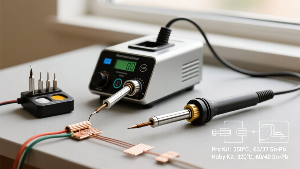
For traditional 63/37 eutectic tin-lead solder (melting point 183°C), set your iron soldering kit to 300°C - 320°C. This provides enough thermal headroom to form a joint in 2-3 seconds without burning the flux. For SAC305 lead-free solder (melting point 217°C), you must increase the temperature to 350°C - 380°C. Lead-free alloys have poorer wetting characteristics and higher surface tension; using a larger chisel tip (like a C4 or D24) rather than a fine point is crucial to maximize thermal transfer to the pad and prevent cold joints.
Final Thoughts on Workspace Optimization
Your workspace is an extension of your iron soldering kit. By investing in proper localized fume extraction, ANSI-compliant ESD matting, high-CRI lighting, and ergonomic board holders, you transition from merely 'melting metal' to executing reliable, professional-grade electronic assemblies. Regular maintenance of your environment—cleaning the mat with an ESD-safe solvent, tinning your tips before powering down, and monitoring your carbon filters—will ensure your bench remains a safe, productive hub for years to come.
Sources & Further Reading:
1. Cornell University EHS: Soldering Safety Guidelines
2. ESD Association: ANSI/ESD S20.20 Standards
3. OSHA: Lead Exposure and Safety Standards