
The JBC Cartridge Advantage in a Modern Electronics Lab
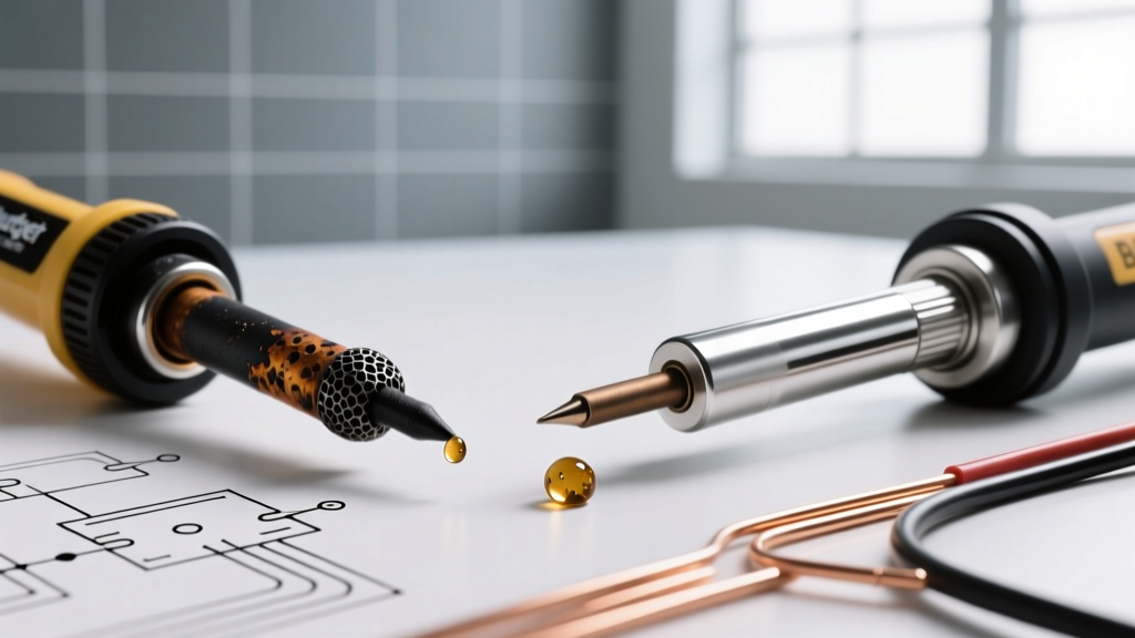
Setting up a professional electronics workspace in 2026 demands precision, speed, and ergonomic foresight. When transitioning from entry-level stations to high-end laboratory equipment, the JBC cartridge-based soldering system stands as the industry benchmark. Unlike traditional screw-in tips where the heating element is separated from the tip by an air gap, JBC soldering tips integrate the heater and thermocouple directly into the disposable cartridge. This proprietary design yields a thermal response time of under two seconds, effectively eliminating cold joints on high-thermal-mass ground planes.
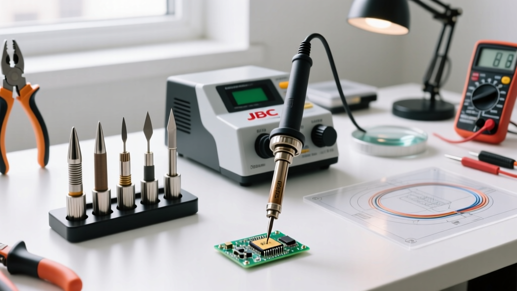
However, simply purchasing a flagship station like the JBC CD-2BQF (typically priced between $620 and $680) is only the first step. Maximizing this technology requires a deliberate workspace setup, precise cartridge selection, and rigorous maintenance protocols aligned with the IPC J-STD-001 standard for soldered electrical assemblies. This guide details how to integrate, select, and maintain JBC soldering tips for peak laboratory performance.
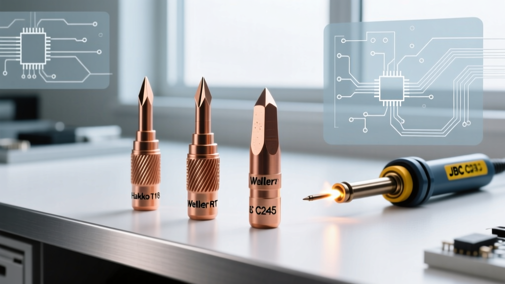
Decoding the JBC Ecosystem: C115, C210, and C245 Cartridges
JBC categorizes its handpieces and corresponding tips into three primary series based on wattage and physical scale. Selecting the correct series for your specific PCB rework tasks is critical to preventing thermal damage to sensitive components.
| Cartridge Series | Max Wattage | Temp Range | Primary Use Case | Avg. Tip Cost (2026) |
|---|---|---|---|---|
| C115 | 15W | 150°C - 450°C | Micro SMD, 01005 passives, micro-jumpers | $55 - $65 |
| C210 | 65W | 150°C - 450°C | Precision SMD, 0402/0603, QFP drag soldering | $50 - $60 |
| C245 | 130W | 150°C - 450°C | Through-hole, heavy ground planes, thick wires | $45 - $55 |
Pro Workspace Tip: Never use a C245 cartridge at maximum temperature to compensate for poor thermal transfer on micro-components. The excessive mass will crush delicate pads. Instead, switch to a C210 handpiece and rely on the station's rapid thermal recovery.
Workspace Integration: Ergonomics and Fume Management
A high-end soldering cartridge is only as effective as the environment it operates in. Proper physical setup reduces operator fatigue and extends tip life.
1. Handpiece Rest and Cable Management
The standard JBC RSA handpiece rest features an integrated brass wool sponge, but its placement on your desk matters. Position the rest exactly 12 to 16 inches from your primary work zone to minimize repetitive strain. For advanced setups, integrate an overhead cable balancer (such as the JBC BPH). Suspending the silicone cord eliminates drag resistance, which is especially critical when using the ultra-thin C115 handpiece for microsurgery-level rework.
2. Fume Extraction Alignment
JBC tips reach operational temperatures in 1.5 seconds, meaning flux off-gassing begins almost immediately upon contact. Position your fume extraction nozzle (e.g., the JBC F-AE system) at a 45-degree angle, approximately 4 inches from the solder joint. This captures the rosin vapor plume before it crosses the operator's breathing zone without cooling the tip via excessive airflow.
Essential JBC Tip Geometries for Specific PCB Tasks
Browsing the JBC Tools official catalog reveals hundreds of tip geometries. To build a versatile workspace, stock these three foundational models:
- C245-945 (2.2mm Chisel): The ultimate workhorse. The 2.2mm width provides enough surface area for standard 0603 components and small through-hole vias, while the chisel edge allows for precise heat direction. Keep this loaded in your primary C245 handpiece.
- C210-107 (0.7mm Conical Bent): Widely considered the holy grail for drag soldering. The 45-degree bend and 0.7mm point allow you to drag solder across 0.5mm pitch QFP and SOIC pins with unparalleled visibility and control.
- C115-112 (0.3mm Blade): Designed for extreme precision. The micro-blade geometry is essential for cutting micro-jumpers, reworking 0.4mm pitch BGA underfills, and soldering 01005 passives under a stereo microscope.
The Maintenance Station: Preventing Oxidation and Sleeve Wear
JBC cartridges are expensive investments. Improper cleaning is the leading cause of premature failure, specifically thermal shock and iron plating degradation.
The "Wipe and Tin" Protocol
- Ditch the Wet Sponge: Traditional wet cellulose sponges drop the tip temperature by up to 150°C instantly. This rapid contraction causes micro-fractures in the iron plating, leading to pitting and solder erosion. Remove wet sponges from your workspace entirely.
- Use Dry Brass Wool: Utilize the JBC BST-A brass wool cleaner. The dry brass shavings remove oxidized flux residue without dropping the tip temperature, preserving the protective iron layer.
- Chemical Tip Tinning: Once per shift, or when the tip exhibits a black, crusty oxidation layer, dip the heated tip into JBC CLT-1A tip cleaner paste for 2 seconds. This chemical compound strips carbon buildup and instantly re-tins the surface.
- Storage Tinning: Before placing the handpiece in the rest for more than 60 seconds, apply a thick blob of 63/37 rosin-core solder to the tip. This sacrificial layer oxidizes in place of the tip's iron plating.
Troubleshooting Common JBC Cartridge Failures
Even in optimized workspaces, edge cases occur. Here is how to diagnose and resolve common JBC-specific hardware issues.
Error: "Heater Not Recognized" on CD-2BQF
Failure Mode: The station display flashes an error and refuses to heat. Solution: This is rarely a dead cartridge. The 5-pin connector on the C245 handle often accumulates microscopic flux residue, disrupting the thermocouple data signal. Unplug the station, remove the cartridge, and clean the internal 5-pin receptor with a lint-free swab and 99% isopropyl alcohol. Allow to dry for 60 seconds before rebooting.
Cartridge Stuck in the Handpiece
Failure Mode: The cartridge sleeve seizes inside the metal handle due to thermal expansion and flux wicking. Solution: Never pull the cartridge by the silicone cord, as this will sever the internal thermocouple wires. Turn off the station and allow the handle to cool to exactly 50°C (warm to the touch, but safe to hold). Use the JBC cartridge removal tool or a pair of smooth-jawed hemostats to grip the cartridge base flange, twisting gently while pulling straight out. Apply a microscopic drop of high-temp anti-seize compound to the new cartridge sleeve before insertion to prevent recurrence.
Frequently Asked Questions
Can I use third-party clone tips with my JBC station?
While cheaper ($10-$15 per tip), third-party clones often lack the precise internal thermocouple calibration. This results in temperature overshoots of up to 40°C, which can delicate multi-layer ceramic capacitors (MLCCs) and compromise IPC compliance. For professional lab environments, genuine JBC cartridges are mandatory.
How long should a genuine JBC C245 tip last?
With proper dry-brass cleaning and consistent tinning, a C245-945 used in a standard production environment should last between 400 and 600 hours of active soldering time. If you notice the iron plating wearing away to reveal the copper core, discard it immediately to prevent copper dissolution into your solder joints.