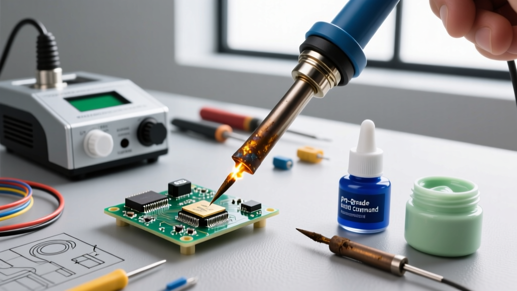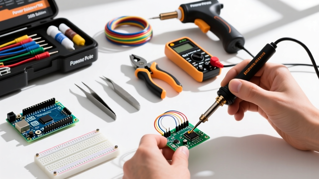

Transitioning from reading schematics to physically building circuits is a major milestone for any electronics enthusiast. However, poor workspace configuration and improper tool selection often lead to frustrating cold joints, damaged components, and abandoned projects. This complete setup tutorial provides essential soldering tips for beginners, focusing on the precise hardware, chemical consumables, and thermal techniques required to consistently produce IPC-compliant through-hole and basic SMD joints.
The Anatomy of a Beginner-Friendly Soldering Station
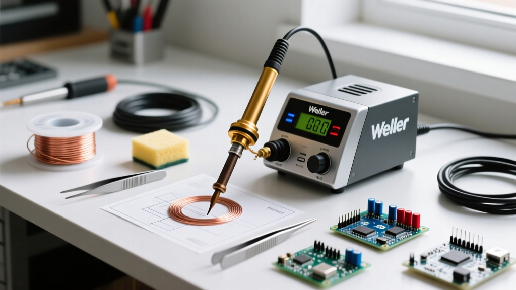
The biggest mistake beginners make is purchasing a cheap, unregulated 40W mains-powered soldering iron. These irons lack thermal recovery, meaning the tip temperature plummets the moment it touches a copper pad, resulting in cold joints. In 2026, you have two highly reliable, budget-conscious paths for a proper temperature-controlled station:
Path A: The Modern Smart Iron (Pine64 Pinecil V2)
Retailing for approximately $26, the Pinecil V2 is a PD (Power Delivery) smart iron. When paired with a 65W USB-C GaN charger (~$20), it utilizes a RISC-V chip to negotiate power and heat a T12-compatible tip to 320°C in under 8 seconds. Its rapid thermal recovery makes it exceptionally forgiving for beginners learning to manage heat transfer.
Path B: The Traditional Workhorse (Hakko FX-888D)
At around $115, the Hakko FX-888D remains the gold standard for traditional bench setups. It uses a T18 tip series and a dedicated AC transformer. While bulkier and slower to heat than the Pinecil, its physical dial interface and rugged build make it a permanent fixture on many professional workbenches.
The Tip Dilemma: Why Conical Tips Fail Beginners
Most entry-level kits include a conical (pointed) tip. This is a critical error in kit packaging. Conical tips possess minimal surface area, drastically reducing thermal transfer efficiency. When a beginner presses a conical tip against a large ground plane, the tip acts as a thermal bottleneck, encouraging the user to press harder and dwell longer—eventually delaminating the PCB pad.
According to Hakko's official tip selection guidelines, maximizing the contact area between the tip and the workpiece is paramount for efficient heat transfer. Beginners should immediately swap to a chisel or bevel tip.
| Tip Geometry | Model Example (T18/T12) | Thermal Mass | Best Application |
|---|---|---|---|
| Conical (Point) | T18-B2 | Low | Avoid: Poor heat transfer for beginners |
| Chisel | T18-D24 (2.4mm) | High | Standard through-hole, thick wires, large pads |
| Bevel / Hoof | T18-C4 | Medium-High | Drag soldering, large SMD pads, scooping solder |
| Knife | T12-K | Medium | 0805 SMD components, tight pitch ICs |
Workspace Configuration & Safety Protocol
A proper physical setup prevents collateral damage to your desk and your lungs. Your bench must include a 500°C rated silicone mat (typically 150mm x 200mm, costing around $12) to protect the underlying surface from stray molten solder drips.
More importantly, you must manage flux off-gassing. When rosin-based flux reaches its activation temperature (usually around 180°C–200°C), it vaporizes into visible smoke containing colophony. Prolonged exposure without extraction is a severe health hazard.
"Soldering fumes contain colophony (rosin), which is a known respiratory sensitizer. Local exhaust ventilation (LEV) or fume extractors with activated carbon filters are mandatory to prevent occupational asthma and respiratory irritation." — Cornell University Environmental Health and Safety
Beginner Setup Requirement: Purchase a desktop fume extractor with a replaceable activated carbon filter (e.g., Hakko FA-400 or a generic equivalent for ~$35). Position the intake fan exactly 4 to 6 inches away from the soldering zone to capture the thermal plume before it reaches your face.
Consumables: Solder Alloy and Flux Chemistry
The metallurgical composition of your solder wire dictates your required iron temperature and the behavior of the molten joint.
Why 63/37 Leaded Solder is Mandatory for Beginners
While lead-free (SAC305) solder is required for commercial manufacturing, beginners should exclusively use 63% Tin / 37% Lead (63/37) rosin-core solder. This specific ratio is eutectic, meaning it transitions directly from solid to liquid at exactly 183°C (361°F) without passing through a plastic (semi-solid) state. This eliminates the risk of disturbing the joint while it cools, which is the primary cause of grainy, high-resistance cold joints.
Recommended Specification: Kester 44 or MG Chemicals 63/37, 0.031" (0.8mm) diameter. The 0.031" thickness provides the perfect volume per inch for standard 2.54mm pitch through-hole components without accidentally flooding the pad.
Step-by-Step: Executing the Perfect Through-Hole Joint
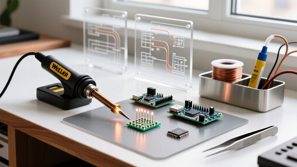
Follow this exact thermal sequence to achieve a concave, shiny, IPC-A-610 compliant fillet. For standard FR4 PCBs, set your iron to 320°C (608°F). FR4 glass transition temperature (Tg) is typically around 130°C–150°C; excessive dwell times will cause the copper pad to lift off the fiberglass substrate.
- Clean and Tin the Tip: Plunge the hot tip into a brass wire sponge (never use a wet cellulose sponge, as the thermal shock micro-fractures the tip's iron plating). Apply a tiny amount of 63/37 solder to the tip to create a shiny protective layer.
- Apply Heat to the Pad AND Lead: Place the flat side of the chisel tip so it simultaneously touches the copper PCB pad and the component's metal lead. Hold for exactly 2 to 3 seconds to allow the thermal mass of both parts to reach soldering temperature.
- Feed the Solder: Touch the solder wire to the opposite side of the pad/lead junction (not directly to the iron tip). The heat from the workpiece should melt the solder. Feed enough solder to form a small concave volcano shape (usually 1 to 1.5 seconds of feed time).
- Remove Solder, Then Remove Iron: Pull the solder wire away first, then smoothly sweep the iron away at a 45-degree angle. This final motion pulls excess solder up onto the tip, leaving a perfect fillet on the pad.
- Do Not Disturb: The joint will solidify in roughly 2 seconds. Do not blow on it or move the component during this phase.
For a comprehensive visual breakdown of these metallurgical phases, refer to Adafruit's Excellent Soldering Guide, which remains one of the most accurate open-source visual references for joint wetting dynamics.
Troubleshooting Common Beginner Failure Modes
Even with the right setup, specific physical anomalies will occur. Here is how to diagnose and correct them:
- The "Icicle" or Blob: Cause: Iron temperature too low, or flux burned off before wetting occurred. Fix: Increase temp by 15°C, clean the tip, and apply external liquid rosin flux to the pad before re-heating.
- Grainy / Dull Joint: Cause: The component was bumped while the eutectic alloy was transitioning from liquid to solid, disrupting the crystalline lattice. Fix: Reheat the joint with a drop of fresh flux until fully liquid, hold perfectly still, and remove heat.
- Lifted Copper Pad: Cause: Dwell time exceeded 5-7 seconds, melting the epoxy bond beneath the copper. Fix: Stop immediately. The pad is destroyed. You must scrape the solder mask off the adjacent trace and run a jumper wire (bodge wire) to bypass the ruined pad.
- Solder Refuses to Stick (Non-Wetting): Cause: Heavy oxidation on the component lead or a nickel-plated surface that lacks sufficient flux activity. Fix: Apply a generous amount of tacky flux (e.g., Amtech NC-559) and use the chisel tip to gently "scrub" the pad while heating.
Maintenance: Prolonging Tip Life
Soldering tips are constructed from a copper core, plated with iron to resist solder erosion, and finally coated with chromium. Leaving a tip bare at 350°C causes the iron plating to oxidize rapidly, turning black and refusing to transfer heat. The Golden Rule: Always leave a large blob of cheap, rosin-core solder covering the entire working surface of the tip before powering down the station. This sacrificial solder layer oxidizes instead of the iron plating, ensuring your tip is ready to use the moment you turn the station back on.