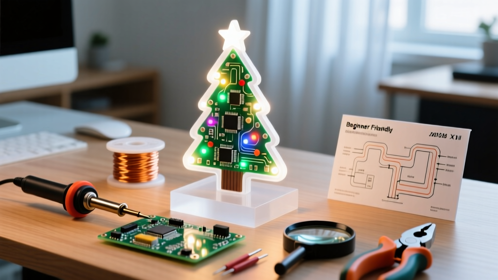

The Appeal of the Christmas Tree Soldering Kit
For novice makers and electronics students, a Christmas tree soldering kit represents the perfect intersection of holiday spirit and foundational skill-building. Unlike abstract practice boards that result in a discarded PCB, a DIY LED tree yields a functional, decorative circuit. In 2026, these kits have evolved from simple static LED arrangements to complex, multi-layered 3D boards featuring astable multivibrator circuits, color-cycling RGB diodes, and integrated audio chips.
However, not all kits are created equal. Cheaply manufactured boards with poor silkscreening and oxidized pads can turn a fun afternoon project into a frustrating exercise in desoldering wick. This guide breaks down the best kits on the market, the exact tools you need, and the circuit theory required to troubleshoot when half your tree refuses to light up.
What to Look for in a Beginner DIY Electronics Kit
When evaluating a kit, look past the flashy packaging and inspect the technical specifications:
- PCB Quality: Look for boards with a HASL (Hot Air Solder Leveling) or ENIG (Electroless Nickel Immersion Gold) finish. Avoid unmarked, dull-looking copper pads which indicate oxidation.
- Silkscreen Clarity: A good kit clearly marks component outlines and polarity indicators (the flat edge for LEDs, the stripe for electrolytic capacitors).
- Component Tolerances: Quality kits include 5% tolerance carbon film resistors with clear, readable color bands.
2026 Comparison: Top Christmas Tree Soldering Kits
We tested the most popular kits available this year to see which offers the best educational value and build experience.
| Kit Model | Component Count | Circuit Type | Price Range (2026) | Best For |
|---|---|---|---|---|
| Gikfun 3D LED Tree | ~75 | Astable Multivibrator | $13 - $16 | Learning transistor switching |
| ICStation DIY Colorful Tree | ~50 | Integrated Circuit (IC) | $10 - $14 | Quick, high-reward builds |
| Elenco AmeriKit Learn to Solder | ~40 | Static/Basic Flash | $18 - $22 | Absolute beginners & classrooms |
Deep Dive: Gikfun 3D LED Tree
The Gikfun kit remains a staple because it forces the builder to understand spatial component placement. The interlocking PCB slots require you to leave specific lead lengths untrimmed until the final mechanical assembly. The circuit relies on two S8050 NPN transistors and cross-coupled 10µF electrolytic capacitors to create the flashing effect.
Essential Toolkit: What You Need Beyond the Box
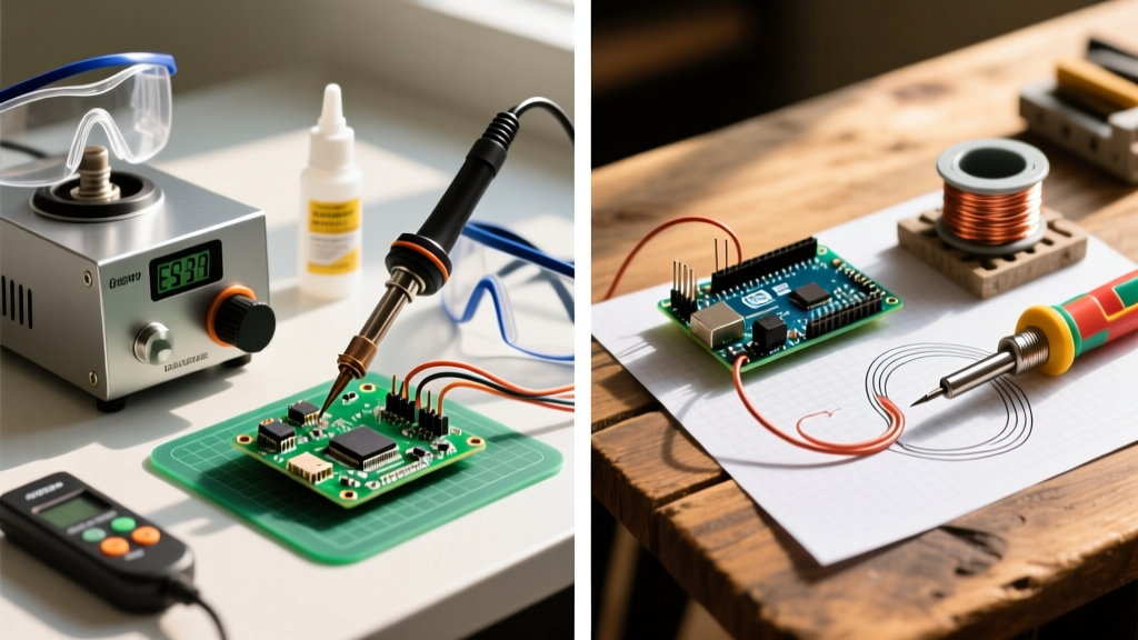
Most Christmas tree kits include only the components and PCB. To achieve reliable, IPC-A-610 compliant solder joints, you need a dedicated workstation. Do not rely on the cheap, unregulated 40W irons sometimes bundled in 'mega kits.'
- Soldering Iron: A temperature-controlled station (like the Hakko FX888D or the portable Pinecil V2) set to 320°C (608°F) for leaded solder.
- Solder Alloy: Use 63/37 Sn/Pb (Tin/Lead) eutectic solder with a rosin core. At 0.8mm diameter, it melts at a single temperature (183°C), eliminating the 'plastic' semi-solid phase of lead-free alloys that causes cold joints when the iron is removed too early.
- Flux: Additional no-clean or rosin flux paste (e.g., Amtech or MG Chemicals) is crucial for reworking bridges on tight transistor pads.
- Side Cutters & Tweezers: Flush cutters for trimming leads, and ESD-safe tweezers for holding small resistors.
For a comprehensive visual walkthrough on through-hole techniques, refer to the SparkFun through-hole soldering tutorial.
Understanding the Astable Multivibrator Circuit
To truly master the Christmas tree soldering kit, you must understand the engine driving the flashing lights: the astable multivibrator. Unlike a monostable circuit that requires a trigger, an astable circuit has no stable state. It continuously oscillates between two states, driven by the charging and discharging of capacitors.
In a standard 3D tree kit, you will find two NPN transistors (often the S8050 or 2N3904). The collector of Transistor A is connected to the base of Transistor B via a resistor, and the emitter/base junction is tied to an electrolytic capacitor. When power is applied, slight manufacturing asymmetries cause one transistor to conduct slightly more than the other. This imbalance is amplified, rapidly driving one transistor into saturation (fully ON) and the other into cutoff (fully OFF). The capacitor connected to the OFF transistor begins to charge through a high-value resistor (usually 100kΩ). Once the capacitor reaches roughly 0.7V, it provides enough base current to turn the second transistor ON, which instantly flips the state of the circuit. This continuous flip-flop is what creates the alternating flash of the LED branches.
Understanding this timing mechanism is crucial for troubleshooting. If your tree flashes too fast or too slow, it is rarely a software error (as there is no microcontroller). It is almost always caused by swapping the 10µF and 47µF capacitors, which directly alters the RC time constant (T = R × C).
Assembly Strategy: Avoiding the 'Dark Branch' Failure
The most common point of failure in a Christmas tree soldering kit is a 'dark branch'—a section of LEDs that fails to illuminate or flash. This is rarely a bad LED; it is almost always a polarity or joint issue.
Step 1: Component Sorting and Height Profiling
Always solder components from lowest profile to highest. Start with the resistors and diodes, move to the IC sockets (if applicable), then the transistors, and finish with the tallest components: the electrolytic capacitors and LEDs. This prevents the board from rocking on your workbench while you try to solder flat components.
Step 2: The LED Polarity Trap
LEDs are diodes; they only allow current to flow in one direction. The physical indicators are:
- Lead Length: The longer leg is the Anode (positive).
- Flat Edge: The plastic lens has a flattened edge at the base, which corresponds to the Cathode (negative).
- Internal Structure: The larger metal 'flag' inside the LED is the Cathode.
Warning: Some budget manufacturers mix up the lead lengths during packaging. Always trust the flat edge and the internal flag over the lead length. Match the flat edge to the shaded silkscreen half on the PCB.
Step 3: Soldering the Flashing Transistors
The astable multivibrator circuit relies on the precise timing of the RC (Resistor-Capacitor) network switching the transistors on and off. The S8050 transistors have three tightly spaced legs (Emitter, Base, Collector). If you use too much solder, you will bridge the Base and Collector pads. If this happens, the transistor remains permanently 'on,' and the corresponding half of the tree will stay lit solidly without flashing.
Expert Tip: If you bridge the pads, do not just drag the iron through it. Apply a drop of fresh liquid flux, use a copper desoldering wick to absorb the excess solder, and re-tin the pads before trying again. The Adafruit Guide to Excellent Soldering emphasizes that flux is the true hero of rework.
Troubleshooting: When the Tree Won't Light Up
If you apply power (usually 3x AA batteries or a 5V USB cable) and nothing happens, follow this diagnostic path:
- Check the Power Switch: Use a multimeter in continuity mode. Ensure the switch actually bridges the power rails when toggled.
- Inspect the Battery Contacts: The metal spring contacts on cheap kits often have a clear anti-corrosion coating that resists solder. Scrape the soldering area with a fiberglass scratch pen before tinning.
- The 'Finger Test': If the tree is static but won't flash, gently touch the metal casing of the two main transistors with your finger. The 60Hz/50Hz mains hum and your body's capacitance can sometimes 'kickstart' a marginal astable multivibrator circuit into oscillating. If it starts flashing while you touch it, one of your electrolytic capacitors is likely inserted backward or has a leaked dielectric.
Frequently Asked Questions
Can I use lead-free solder for my Christmas tree kit?
You can, but it is not recommended for beginners. Lead-free solder (like SAC305) requires higher iron temperatures (around 350°C - 380°C) and has a tendency to create dull, grainy joints that look like cold joints to an untrained eye. Stick to 63/37 eutectic leaded solder for your first few kits.
Why did my LED pop and go dark?
LEDs have a maximum reverse voltage rating (usually around 5V). If you install an LED backward in a circuit that pushes 5V or more across it during the 'off' cycle of the multivibrator, it will suffer avalanche breakdown and pop. Always double-check polarity before applying power.
How do I safely store the finished tree?
Apply a light coat of acrylic conformal spray to the bottom of the PCB to prevent dust and moisture from causing dendritic growth (short circuits) over time. Store it in a rigid plastic container with foam padding to prevent the fragile LED leads from snapping.