
The Physics of the Chisel Soldering Tip
Despite the proliferation of specialized micro-tips and hot-air rework stations in 2026, the standard chisel soldering tip remains the undisputed workhorse of the electronics assembly bench. Unlike conical tips, which suffer from poor thermal transfer due to a minimal point of contact, a chisel tip maximizes surface area. This geometry allows for rapid thermal conduction directly into the copper pad and the component lead simultaneously.
The standard bevel angle of a chisel tip typically ranges between 45 and 60 degrees. This specific geometry is not arbitrary; it provides an optimal balance between edge precision for surface-mount device (SMD) alignment and flat-surface thermal mass for absorbing the heat sink effect of multi-layer printed circuit boards (PCBs). When you press the flat face of a Hakko T18-D24 (2.4mm width) against an 0805 resistor pad, the heat transfers in milliseconds, preventing the thermal degradation of the component's internal die.
Unboxing and Inspection: What to Look For
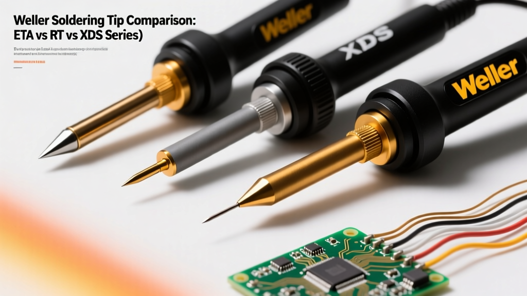
Before installing your new chisel tip, a thorough inspection is critical. Counterfeit tips have flooded the market, often lacking the internal copper core and iron plating required for longevity. A genuine tip, such as the Weller ETA or Hakko T18 series, will feature a seamless iron plating over a solid copper core, usually priced between $8.00 and $14.00 USD depending on the brand and retailer.
- Surface Finish: The working end should have a dull, matte-grey finish. A highly reflective, mirror-like finish often indicates cheap chrome plating, which solder will not wet.
- Shaft Tolerance: The inner diameter of the tip shaft must slide smoothly over your station's ceramic heating element. Forcing a poorly machined counterfeit tip can crack the fragile alumina ceramic heater, resulting in a $30+ replacement cost.
- Flux Residue: New tips are often coated in a thin layer of manufacturing oil or anti-oxidation flux. This must be cleaned during the initial seasoning phase.
Step-by-Step Installation Protocol
Proper installation ensures optimal thermal coupling between the heating element and the tip. Poor coupling leads to temperature lag, causing operators to dangerously overcompensate by cranking up the station's heat dial.
- Power Down and Cool: Ensure the soldering station is completely unplugged and the heater assembly is at room temperature.
- Loosen the Retaining Nut: Using a suitable wrench or by hand, unscrew the front retaining nut and slide off the metal sleeve.
- Slide the Tip: Gently slide the chisel tip over the ceramic heater. Never twist or apply lateral pressure. The tip should slide all the way down until it bottoms out against the heater's shoulder.
- Replace the Sleeve and Nut: Slide the metal sleeve back over the tip shaft and thread the retaining nut.
- Apply Correct Torque: Tighten the nut finger-tight, then use a wrench to turn it an additional one-quarter turn. Over-tightening will crush the metal sleeve and crack the ceramic element underneath.
The Crucial First Step: Tinning and Seasoning
The moment you power on a brand-new chisel tip is the most dangerous phase of its lifecycle. If the bare iron plating reaches soldering temperatures without a protective layer of solder, it will oxidize instantly, turning black and refusing to accept solder—a condition known as 'dry heating'.
Critical Warning: Never wipe a brand-new, dry tip on a damp sponge before applying solder. The thermal shock combined with oxidation will permanently ruin the iron plating before your first joint.
The Seasoning Procedure:
- Set your station to a low temperature, approximately 250°C (482°F) if using leaded solder, or 300°C (572°F) for lead-free SAC305.
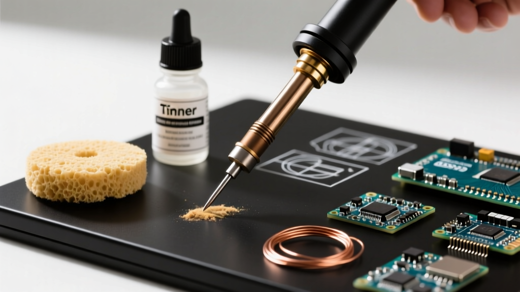
- As the tip begins to warm up (around 150°C), aggressively feed a thick, rosin-core solder wire (such as Kester 44 or MG Chemicals 4884) onto the entire working surface of the chisel.
- Allow the solder to melt and pool, completely encapsulating the bevel and the flat faces.
- Once fully coated, increase the station to your standard working temperature and wipe gently on a brass wool sponge.
- Apply a fresh layer of solder before setting the iron into its holder. This sacrificial layer will oxidize instead of the tip's iron plating.
Application Matrix: Matching Tip Width to Joint Geometry
Selecting the correct chisel width is just as important as temperature control. A tip that is too narrow will lack the thermal mass to heat a heavy ground plane, while a tip that is too wide risks bridging adjacent pins or melting nearby plastic connectors. Refer to the matrix below for standard 2026 assembly guidelines.
| Application / Joint Type | Recommended Tip Model | Tip Width | Target Temp (SAC305) | Max Dwell Time |
|---|---|---|---|---|
| 0603 / 0805 SMD Passives | Hakko T18-D16 / JBC C115-114 | 1.6mm | 340°C - 350°C | 1.5 - 2.0 seconds |
| Standard DIP / Through-Hole | Hakko T18-D24 / Weller ETA | 2.4mm | 350°C - 360°C | 2.0 - 3.0 seconds |
| Heavy Wire (14-18 AWG) | Hakko T18-D32 / Weller ETC | 3.2mm | 360°C - 380°C | 3.0 - 4.0 seconds |
| Multi-Layer Ground Planes | Hakko T18-D52 / Weller EER | 5.2mm+ | 380°C - 400°C | 4.0 - 5.0 seconds |
For comprehensive industry standards regarding dwell times and thermal profiles, refer to the IPC Standards for Electronic Assemblies, specifically IPC J-STD-001, which dictates the requirements for soldered electrical and electronic assemblies.
Troubleshooting Common Chisel Tip Failure Modes
Even with meticulous care, chisel tips will eventually degrade. Understanding the failure modes allows you to salvage a tip or know when to discard it.
1. Severe Oxidation (The 'Black Crust')
Symptom: Solder balls up and rolls off the tip; the working surface appears dark grey or black. Cause: Leaving the iron idle at high temperatures without a sacrificial solder coating, or using highly activated, corrosive fluxes without cleaning. Solution: Use a specialized tip tinner (like Hakko 599B brass wool with embedded flux). Never use sandpaper, files, or abrasive pads. According to Hakko's official maintenance guidelines, abrasive cleaning removes the microscopic iron plating, instantly destroying the tip.
2. Pitting and Concave Wear
Symptom: The flat face of the chisel develops microscopic craters or a scooped-out, concave shape. Cause: The iron plating has been breached, and the underlying copper core is dissolving into the tin-lead or SAC alloy. High-tin lead-free solders are particularly aggressive at dissolving copper. Solution: The tip is dead. Once the copper is exposed, thermal transfer becomes erratic, and the tip will physically degrade. Replace the tip immediately.
3. Solder Bridging and Flux Carbonization
Symptom: A hard, black, glassy residue builds up on the sides of the chisel, preventing heat transfer. Cause: Burnt rosin flux. Solution: While the tip is at operating temperature, wipe it firmly through a damp cellulose sponge. The steam generated helps lift the carbonized flux. Follow immediately with fresh solder.
Advanced Maintenance and Storage Protocols
To maximize the lifespan of your chisel soldering tip, integrate these habits into your daily workflow:
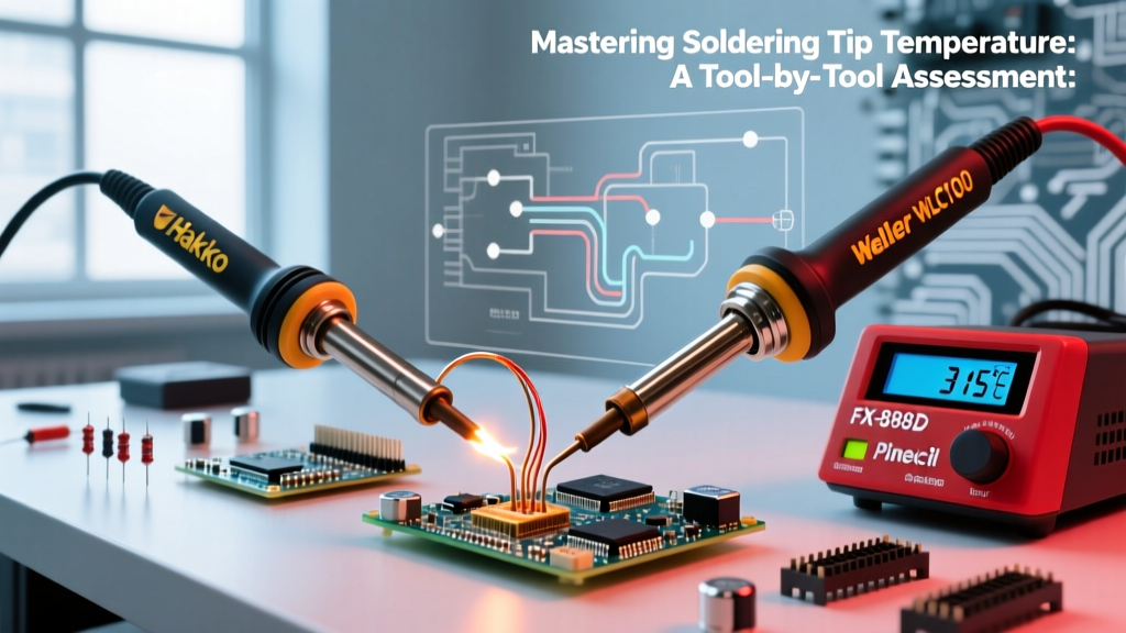
- Utilize Sleep Mode: Modern stations like the Weller WE1010NA or Hakko FX-951 feature auto-sleep. Configure your station to drop the temperature to 200°C after 5 minutes of inactivity. This drastically slows oxidation.
- The 'Sacrificial Blob' Rule: Before placing the iron back into the cradle, always melt a large blob of solder onto the chisel face. This acts as a sacrificial anode; the oxygen in the air will oxidize the solder blob rather than the tip's iron plating. Wipe it clean only when you are ready to make the next joint.
- Match Flux Chemistry: If you are using no-clean flux (such as Amtech NC-559), avoid leaving the residue on the tip. While 'no-clean' refers to the PCB assembly, the halides and organic acids can still corrode the tip plating when subjected to continuous high heat.
Frequently Asked Questions
Can I use a chisel tip for drag soldering fine-pitch ICs?
Yes, a narrow chisel tip (1.0mm to 1.6mm) is actually preferred by many professionals for drag soldering fine-pitch (0.5mm or 0.65mm) QFP and TSSOP packages. The flat edge allows you to control the solder meniscus and drag it smoothly across the pins, whereas a conical tip tends to snag and bridge.
Why does my new chisel tip turn blue and purple?
This discoloration on the non-working shaft of the tip is normal. It is caused by the tempering colors of the metal reacting to the heat gradient. As long as the actual working bevel remains shiny and tinned, the tip is perfectly functional. For more visual troubleshooting, the SparkFun Through-Hole Soldering Tutorial offers excellent photographic examples of tip wetting and thermal gradients.
Is a 'bevel' tip the same as a chisel tip?
No. A standard chisel tip has a symmetrical V-shaped edge, providing two usable flat faces and a sharp point. A bevel tip (or hoof tip) is cut at an angle, presenting a single flat, oval-shaped working surface. Bevel tips are excellent for drag soldering and holding large solder volumes, but they lack the dual-sided versatility and precision point of a true chisel tip.