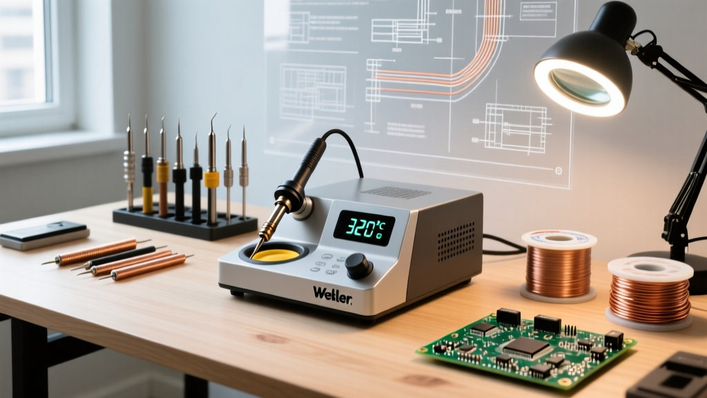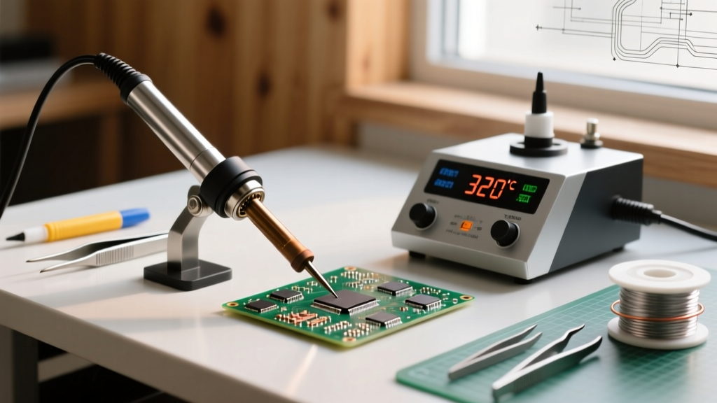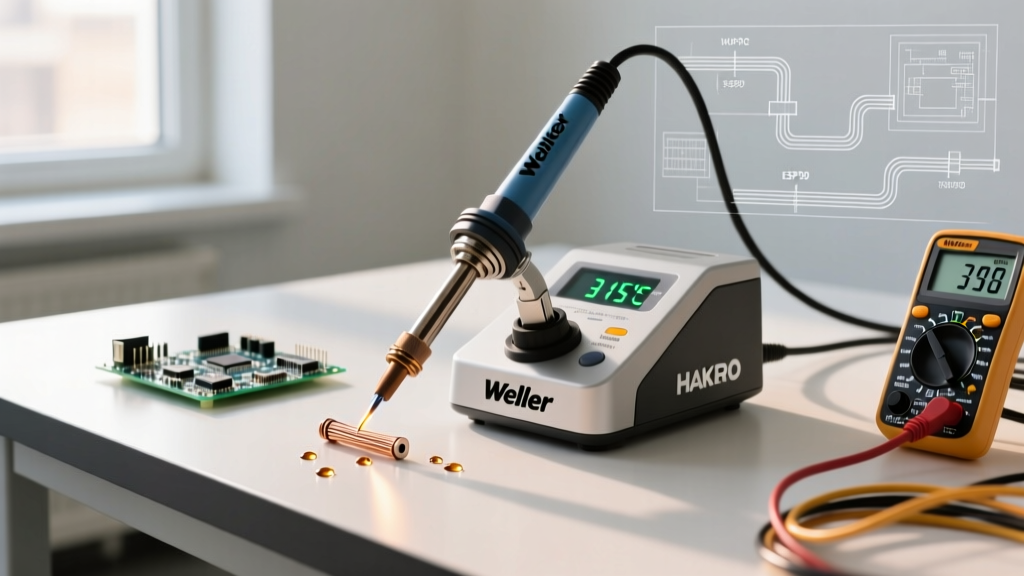

The Core Question: What Temperature to Set Soldering Iron?
Ask any forum what temperature to set soldering iron to, and you will inevitably get a blanket answer of 350°C (662°F). As a senior electronics technician, I can tell you that this generic advice is a fast track to lifted pads, oxidized tips, and burnt flux. The correct temperature is not a single number; it is a dynamic variable dictated by solder alloy, thermal mass, tip geometry, and the PID controller of your soldering station.
In 2026, the market is split between legacy ceramic-heater workhorses and modern direct-drive cartridge systems. To help you dial in the perfect heat profile, we are comparing how the industry's best stations handle temperature settings, thermal recovery, and real-world edge cases.
Baseline Temperature Matrix by Solder Alloy
Before touching a dial, you must understand the metallurgy of your solder. The general rule of thumb is to set your iron 100°C to 150°C above the liquidus (melting) point of the alloy. According to the IPC J-STD-001 standard, proper wetting requires sufficient thermal transfer, not just surface melting.
| Solder Alloy | Composition | Melting Point | Ideal Iron Temp (Small Pads) | Ideal Iron Temp (High Mass) |
|---|---|---|---|---|
| Leaded Eutectic | Sn63/Pb37 | 183°C (361°F) | 300°C - 320°C | 330°C - 350°C |
| Lead-Free (Standard) | SAC305 | 217°C - 220°C | 340°C - 360°C | 370°C - 390°C |
| Low-Temp Lead-Free | Sn42/Bi57/Ag1 | 138°C (280°F) | 220°C - 250°C | 260°C - 280°C |
| High-Temp (Hi-Rel) | Sn10/Pb88/Ag2 | 268°C (514°F) | 380°C - 400°C | 410°C - 430°C |
2026 Station Showdown: Thermal Recovery & Control
Setting the dial to 350°C means nothing if the station cannot maintain that temperature when the tip touches a copper ground plane. Here is how the top-tier stations compare in thermal management and pricing for 2026.
| Station Model | Avg. Price (2026) | Heater Tech | Temp Range | Thermal Recovery (to 350°C) | Best For |
|---|---|---|---|---|---|
| Pinecil V2 | $29 | Direct DC / PD 3.1 | 100°C - 450°C | ~3 seconds (at 245W) | Hobbyists, Field Repair |
| Hakko FX-888D | $115 | Ceramic (T18 Tips) | 120°C - 480°C | ~18 seconds | General Through-Hole |
| Weller WE1010NA | $135 | Ceramic (ET Tips) | 50°C - 450°C | ~12 seconds | Precision SMD / Lab Use |
| JBC CD-2BQE | $695 | Cartridge (Direct Drive) | 90°C - 450°C | < 2 seconds | Heavy Ground Planes, Pro SMD |
Deep Dive: How the Leaders Handle Heat
- JBC CD-2BQE: JBC integrates the heater and sensor directly into the tip cartridge. When you ask "what temperature to set soldering iron" for a massive 12-layer motherboard ground plane, JBC is the answer. The integrated thermocouple detects heat loss instantly, feeding the PID controller to dump power before the joint starves.
- Weller WE1010NA: Weller’s proprietary sensor placement sits millimeters from the tip apex. It excels at delicate 0402 SMD work where overshooting by even 10°C can melt plastic component housings.
- Pinecil V2: Powered by a RISC-V chip, the open-source Pinecil leverages USB-C Power Delivery 3.1 (up to 245W with the right brick). It bridges the gap between budget and pro, offering JBC-like recovery times for a fraction of the cost, though tip longevity is slightly lower.
Task-Specific Temperature Profiles
Dialing in the exact number requires matching the task to the thermal mass. Here are the field-tested profiles used by NASA Workmanship Standard certified technicians.
1. Delicate SMD Work (0402 to 0805 Components)
Target: 310°C - 330°C (Leaded) / 340°C - 350°C (Lead-Free)
Tip Geometry: Micro-pencil or ultra-fine conical.
Strategy: Small tips have low thermal mass. Do not compensate for a tiny tip by cranking the heat to 400°C; you will oxidize the tip instantly. Instead, use a high-quality flux (like Amtech NC-559) and let capillary action do the work. Keep contact time under 2 seconds per pad.
2. Standard Through-Hole (DIP ICs, Capacitors)
Target: 330°C - 350°C
Tip Geometry: Standard chisel (2.4mm to 3.2mm).
Strategy: A chisel tip maximizes surface area contact with the lead and the barrel of the plated through-hole (PTH). Apply solder to the iron tip to create a thermal bridge, then feed solder into the joint, not the iron.
3. Heavy Ground Planes and Large Connectors
Target: 360°C - 390°C
Tip Geometry: Wide chisel, bevel, or mini-wave (4.0mm+).
Strategy: Ground planes act as massive heat sinks. If your station (like the Hakko FX-888D) struggles to recover, do not just raise the temperature to 450°C, which will scorch the FR4 fiberglass. Instead, use a wider tip to increase thermal transfer, or employ a bottom-side PCB preheater set to 120°C to reduce the thermal delta.
The Hidden Variable: Tip Geometry vs. Temperature Setting
Expert Insight: A 4.0mm chisel tip set to 320°C will melt solder on a heavy ground plane significantly faster and safer than a 0.4mm micro-pencil set to 400°C. Thermal transfer is a product of temperature and surface area. Always maximize tip size before maximizing temperature.
According to the Weller Tools Knowledge Base, using a tip that is too small for the joint forces the operator to dwell on the pad for too long. This prolonged dwell time causes the internal copper layers to delaminate and the solder mask to blister, even if the iron's set temperature is technically within spec.
Failure Modes: When Your Settings Destroy the PCB
Understanding what happens when you get the temperature wrong is crucial for troubleshooting.
- The "Black Crust" (Oxidation): If your tip turns black and refuses to wet with solder, your temperature is too high for the flux chemistry, or you are using lead-free settings on leaded solder. Flux burns off, leaving the iron plating exposed to rapid oxidation. Fix: Drop temp by 30°C and use a brass wool tip cleaner.
- Cold Joints (Grainy/Dull Finish): A dull, lumpy joint indicates the iron was too cold, or the thermal mass of the part sucked the heat away before the flux could activate. The intermetallic compound (IMC) layer fails to form properly. Fix: Increase temp by 20°C or switch to a larger chisel tip.
- Tombstoning (SMD): When one side of a capacitor lifts off the pad. This happens when the temperature is too high on one pad, causing the flux to activate and surface tension to pull the component upright before the other pad melts. Fix: Lower temp slightly and heat both pads simultaneously with a micro-pencil.
Frequently Asked Questions
Should I turn my soldering iron down when not in use?
Yes. Leaving a station at 380°C while idle accelerates tip oxidation and degrades the heating element. Modern stations like the Weller WE1010NA feature auto-standby modes that drop the temperature to 150°C when the iron is holstered, extending tip life by up to 40%.
What temperature to set soldering iron for desoldering?
Desoldering requires slightly higher temperatures (usually +20°C above your soldering temp) because you are trying to melt a larger volume of existing solder while simultaneously operating a vacuum pump or wick, both of which act as heat sinks. For SAC305, set your desoldering gun to 380°C - 390°C.
Does altitude or ambient room temperature affect my settings?
Marginally. High altitudes lower the boiling point of certain liquid fluxes, which can cause them to splatter if the iron is too hot. Cold ambient environments (like an unheated garage in winter) will increase the thermal shock to the PCB, requiring a slight bump in temperature or the mandatory use of a preheater.