
The Core Premise: Electrical Energy to Thermal Transfer
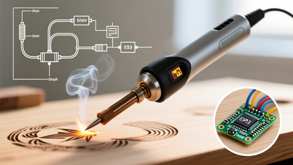
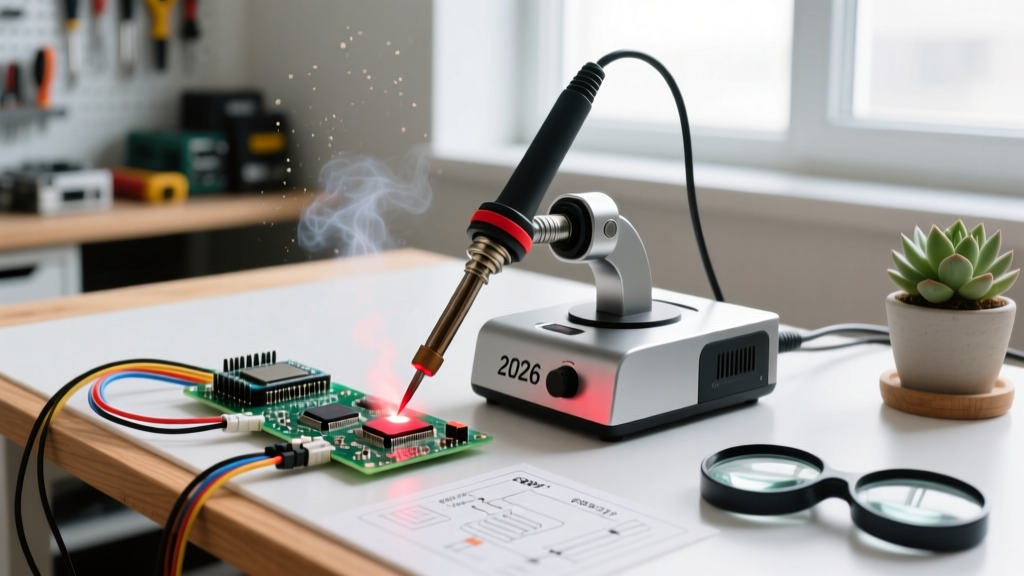
When hobbyists and professionals ask, "how does a soldering iron work?", the simplest answer is that it converts electrical energy into heat, which is then transferred via conduction to a metal joint. However, from an engineering perspective, a modern soldering station is a closed-loop thermodynamic system designed to manage thermal mass, specific heat capacity, and intermetallic compound (IMC) formation. Understanding the physics behind your iron is the difference between creating a reliable, shiny fillet and inducing a brittle cold joint that will fail under thermal cycling.
At the heart of the system is the heating element. When electrical current passes through a resistive material (or induces eddy currents in a ferromagnetic core), it generates thermal energy. This energy must travel through the heating element's casing, across an air gap or thermal paste interface, into the copper core of the soldering tip, and finally into the copper pad and component lead on your PCB. Every interface in this chain introduces thermal resistance.
Heating Element Technologies Compared
Not all heating elements are created equal. The method used to generate and transfer heat dictates the station's recovery time, lifespan, and ultimate price point. Below is a breakdown of the three dominant technologies in 2026.
| Technology | Example Model | Heat-Up Time | Thermal Recovery | Price Range |
|---|---|---|---|---|
| Nichrome Wire (Ceramic Core) | Hakko FX-888D | 20 - 40 seconds | Moderate (Sensor in element) | $100 - $130 |
| Thick Film (Integrated Cartridge) | JBC CD-2BQE (C245 tips) | 2 - 3 seconds | Exceptional (Sensor in tip) | $550 - $700 |
| High-Frequency Induction | Quick 861DW | 10 - 15 seconds | High (Eddy current saturation) | $250 - $350 |
Traditional nichrome wire elements, like those found in the ubiquitous Hakko FX-888D, wrap a resistive wire around a ceramic cylinder. While reliable and inexpensive, the temperature sensor is located inside the heater, not the tip. This means the system measures the heater's temperature, not the actual working end of the tip, leading to a thermal lag when soldering heavy ground planes.
Conversely, premium systems like the JBC CD-2BQE use thick-film printed heaters where the resistive trace and the thermocouple are integrated directly into the consumable C245 tip cartridge. This eliminates the air gap between the heater and the tip, resulting in near-instantaneous thermal recovery and allowing the station to solder heavy multilayer PCB ground planes at lower baseline temperatures, preserving both the tip and the sensitive silicon components.
Thermodynamics of the Tip: Why Wattage is Misleading
A common misconception is that higher wattage equals a better soldering iron. In reality, wattage only dictates the maximum rate of energy input. The actual performance is governed by thermal mass and tip geometry.
According to the principles outlined in Electronics Notes' soldering fundamentals, heat transfer rate ($q$) is proportional to the cross-sectional area of the tip and the thermal conductivity of the materials involved. If you attempt to solder a large copper pour using a 0.5mm conical tip on a 65W iron, the joint will fail. The copper pour acts as a massive heat sink, drawing thermal energy away faster than the narrow tip can replenish it, regardless of the iron's wattage.
Tip Geometry and Surface Area
- Chisel / Screwdriver Tips: Maximum surface area contact. Ideal for through-hole components and large SMD pads. The flat face ensures minimal thermal resistance at the joint interface.
- Conical Tips: Poor thermal transfer due to minimal contact area. Often mistakenly bought by beginners for "precision," but they actually cause cold joints by starving the pad of heat.
- Hoof / Bevel Tips: Excellent for drag-soldering SOIC and QFP integrated circuits. The concave shape holds a small reservoir of molten solder, utilizing the solder itself as a thermal bridge between the iron and the IC pins.
- Knife (K-Tip): Versatile for both precision 0402 work (using the point) and larger pads (using the flat edge).
Closed-Loop Temperature Control: PID vs. Bang-Bang
How does a soldering iron maintain a steady 320°C when the ambient room temperature fluctuates and the iron is constantly losing heat to the air and the PCB? It relies on a feedback loop.
Cheaper irons use a Bang-Bang controller (a simple bimetallic thermostat). The heater turns on at 100% power until the target temperature is reached, then shuts off completely until the temperature drops below a threshold. This causes wild temperature oscillations (e.g., swinging between 290°C and 340°C), which is disastrous for temperature-sensitive components like RF modules or modern BGAs.
Modern smart irons, such as the Pinecil V2 (powered by a RISC-V microcontroller), utilize PID (Proportional-Integral-Derivative) control. The PID algorithm samples the tip temperature multiple times per second and applies pulse-width modulation (PWM) to the heater. As the tip approaches the target temperature, the PID controller proportionally reduces the power, "coasting" to the exact setpoint without overshooting. When the tip touches a cold PCB pad and the temperature drops, the derivative term predicts the thermal deficit and surges power instantly to compensate.
The "Cold Joint" Failure Mode: A cold joint occurs not necessarily because the iron's dial is set too low, but because the thermal mass of the joint exceeded the thermal recovery rate of the tip. The solder melts from the iron's direct contact, but the copper pad remains below the solder's liquidus temperature, preventing the formation of a proper metallurgical bond.
The Metallurgy: Flux Activation and IMC Formation
Understanding how a soldering iron works requires looking at the chemical reactions it enables. Soldering is not "gluing" metal together; it is a micro-welding process that forms an Intermetallic Compound (IMC).
When you apply a 320°C tip to a pad using SAC305 (lead-free) solder, the following sequence occurs in a matter of seconds:
- Flux Activation (150°C - 200°C): The rosin or organic acid flux melts and boils, chemically reducing the copper oxide layer on the PCB pad, exposing pure copper.
- Wetting (217°C+): The solder alloy reaches its liquidus state. The flux lowers the surface tension, allowing the molten tin to "wet" the copper.
- IMC Formation (250°C+): Tin and copper atoms intermingle to form the eta-phase Cu6Sn5 IMC layer. This layer is typically 1 to 3 micrometers thick and provides the mechanical and electrical bond.
If your iron's thermal recovery is poor and the joint lingers in the 200°C–215°C zone for too long, the flux will burn off (oxidize) before the solder fully wets, resulting in a dull, grainy, high-resistance joint. Conversely, if the iron is set excessively high (e.g., >400°C), the IMC layer grows too thick (forming the brittle epsilon-phase Cu3Sn), making the joint prone to mechanical fracturing under vibration.
Real-World Troubleshooting: Heat Transfer Failures
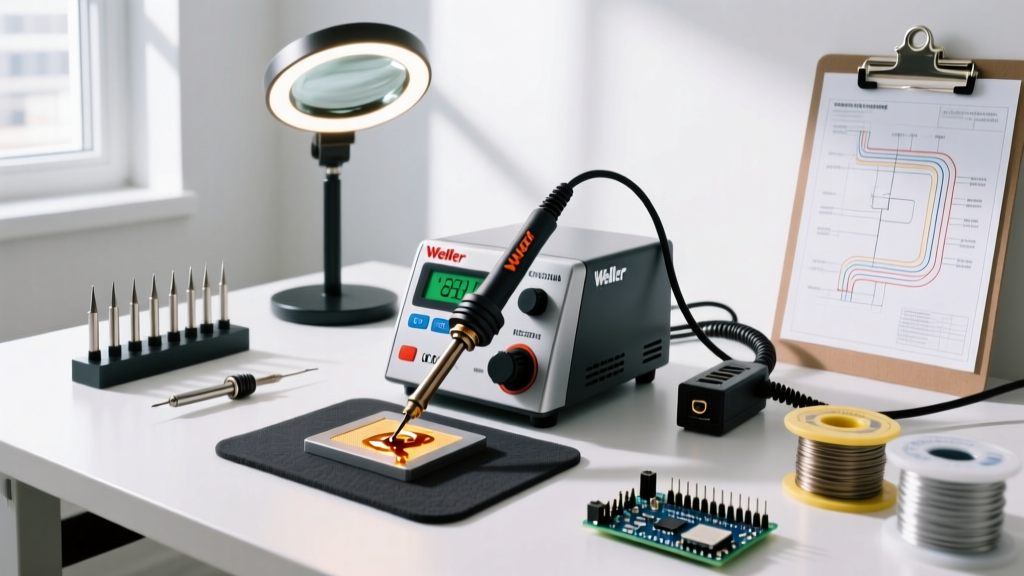
Even with a top-tier station like the Weller WE1010 or a high-end JBC, you will encounter heat transfer failures if you ignore the physical condition of the tip. Here is a diagnostic flow for common thermal issues:
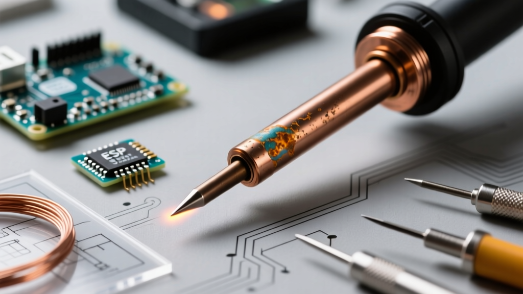
- Solder Balls Up and Falls Off: The tip is oxidized. Iron oxide is a profound thermal insulator. Fix: Never use abrasive sandpaper or steel wool, which strips the microscopic iron plating. Use a damp brass sponge and a generous application of tip tinner (a mixture of solder powder and aggressive flux) to chemically reduce the oxide.
- Component Melts but Pad Won't Take Solder: You are using a tip with too little thermal mass (e.g., a micro-conical tip on a ground plane). Fix: Switch to a wider chisel tip or add a small "solder bridge" using leaded solder to lower the local melting point and increase thermal conductivity to the pad.
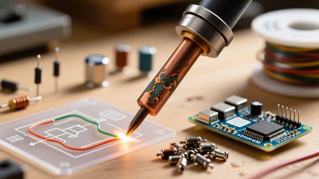
- Tip Pitting and Cratering: Caused by leaving the iron at 400°C+ while idle, or using highly active, corrosive plumbing fluxes on electronics. Fix: Always enable the station's auto-sleep feature (available on most digital stations) to drop the temperature to 150°C when not in use, and strictly use electronics-grade ROL0 or ROL1 fluxes as defined by IPC standards.
Summary: Mastering the Thermal Chain
Ultimately, how a soldering iron works is a lesson in applied thermodynamics. The iron is merely a pump, pushing thermal energy into a system. By matching the correct tip geometry to the joint's thermal mass, utilizing PID-controlled stations to prevent overshoot, and respecting the metallurgical requirements of the solder alloy, you transition from simply melting metal to engineering reliable, long-lasting electrical connections. For further reading on practical through-hole and SMD techniques, SparkFun's comprehensive soldering tutorial remains an excellent visual companion to the physics discussed here.