
The Physics of Curie Heating: Why Induction Changes Your Technique
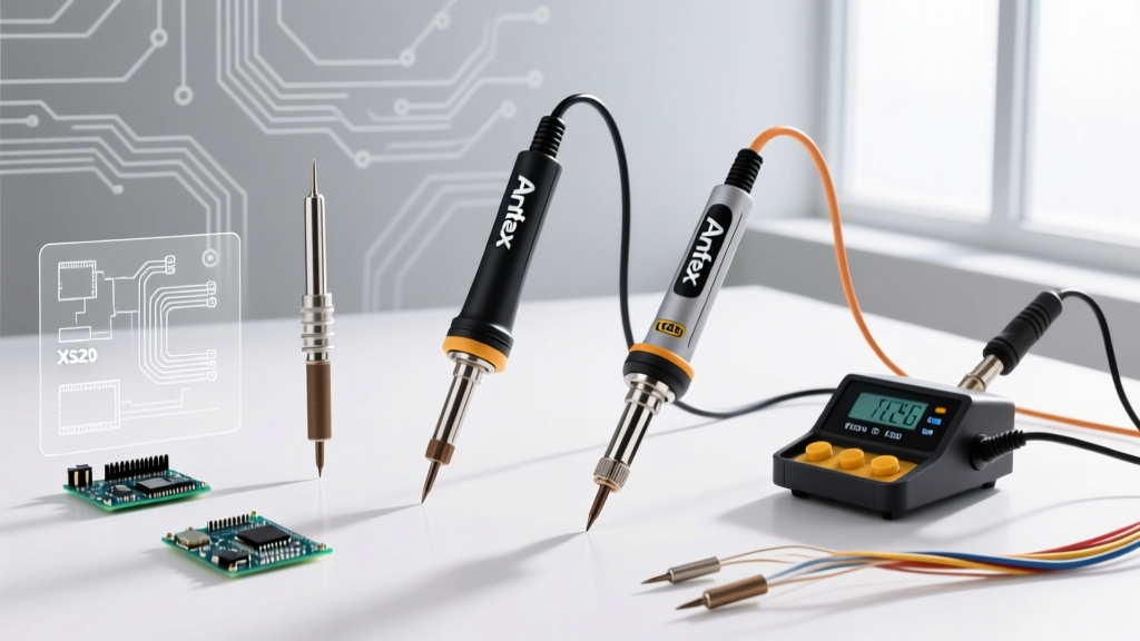
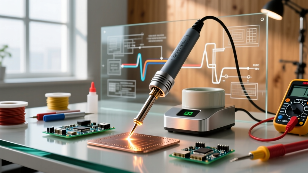
Unlike traditional resistive soldering stations that rely on a ceramic heating element and a thermocouple feedback loop, an induction soldering iron generates heat directly inside the tip itself. This is achieved by passing a high-frequency alternating current (typically at the 13.56 MHz ISM band) through a coil in the handpiece. This creates a rapidly alternating magnetic field, which induces eddy currents in the ferromagnetic core of the soldering tip.
Due to the electrical resistance of the tip's iron cladding, these eddy currents generate intense, localized heat. However, the true genius of the induction soldering iron lies in the Curie temperature (Tc) effect. When the ferromagnetic material reaches its specific Curie point, it loses its magnetic properties. The eddy currents instantly cease, and heating stops. As the tip transfers heat to the PCB and drops below the Tc, it regains its magnetism, and the RF generator resumes heating. This creates a zero-lag, self-regulating thermal loop that eliminates the temperature overshoot common in resistive stations.
2026 Industry Shift: Modern induction stations, such as the latest GaN-driven RF generators, have drastically reduced handpiece weight and electromagnetic interference (EMI) compared to the heavy transformer-based units of the previous decade, making them viable for dense, RF-sensitive aerospace assemblies.
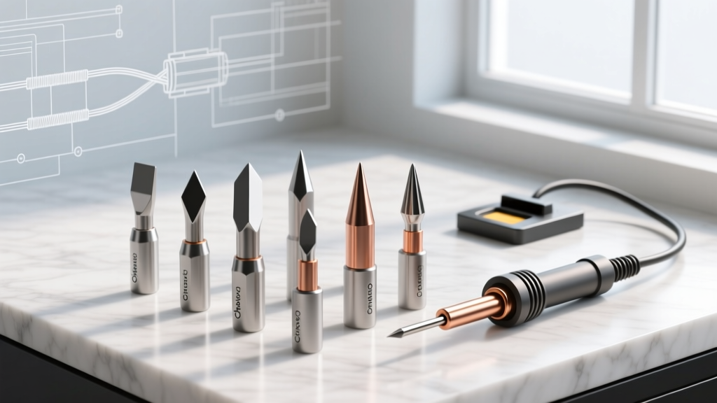
Decoding Tip Metallurgy: Selecting the Right Tc Alloy
In the induction ecosystem, you do not set a temperature on a digital dial. Instead, you select a tip manufactured with a specific ferromagnetic alloy core calibrated to a precise Curie point. Choosing the wrong alloy violates the thermal excursion limits outlined in IPC J-STD-001 for solder joint reliability.
| Tip Series (Color Code) | Curie Temperature (Tc) | Primary Application | Best Suited For |
|---|---|---|---|
| 500 Series (Blue) | 500°F (260°C) | Heat-Sensitive Components | Fine-pitch SMD, flexible circuits, lead-free low-temp alloys (SnBi) |
| 600 Series (Grey) | 600°F (315°C) | Standard General Purpose | Standard through-hole, 0603/0805 SMD, standard SAC305 lead-free |
| 700 Series (Purple) | 700°F (370°C) | High Thermal Mass | Multi-layer PCB ground planes, heavy power connectors, thick wires |
| 800 Series (Red) | 800°F (425°C) | Extreme Mass / Lugs | Automotive wire harnessing, large copper lugs, chassis grounding |
Technique 1: Conquering High-Mass Ground Planes
Soldering a heavy ground plane on a 6-layer PCB is where resistive irons fail and induction irons excel. A 600°F tip will stall against a massive internal copper pour because the heat is wicked away faster than the localized tip face can replenish it. Here is the exact technique for high-mass induction soldering:
- Upgrade to a 700-Series Chisel: Swap your standard 600-series tip for a 700-series wide chisel (e.g., Metcal STTC-117 or Hakko equivalent). The higher Tc provides the necessary thermal delta to push heat into the copper pour.
- Pre-Tin the Pad and Component Lead: Apply a generous amount of tacky flux (like Amtech NC-559) and pre-tin both the PCB pad and the component lead with a small amount of SAC305 solder.
- The 'Wet' Thermal Bridge: Apply the iron to the pad and immediately feed a tiny amount of additional solder wire into the joint. The molten solder acts as a liquid thermal bridge, maximizing surface area contact and transferring the induction heat directly into the ground plane.
- Dwell and Observe: Hold the iron flat against the pad. You will feel the 'pull' of the molten solder wicking into the plated through-hole. Once the solder flows smoothly into the barrel, remove the iron. Total dwell time should not exceed 3 to 4 seconds.
Technique 2: Advanced SMD Drag Soldering
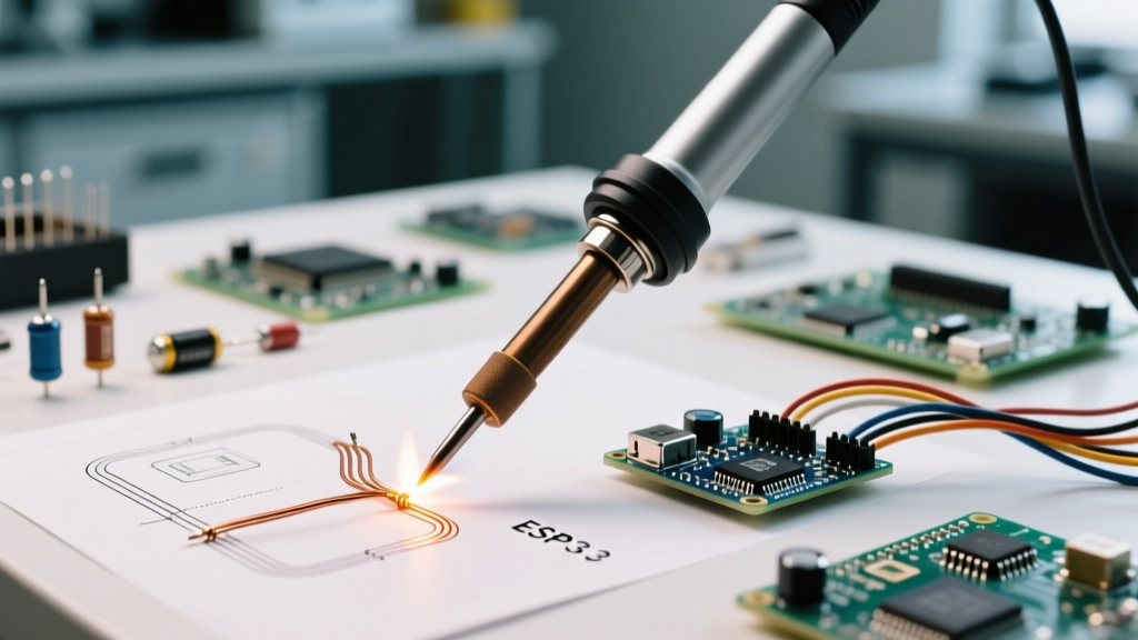
Induction heating provides unparalleled thermal recovery during drag soldering on fine-pitch ICs (like QFP-144 packages). Because the heat is generated in the outer 0.5mm of the tip (due to the skin effect of the RF field), the working face recovers instantly as you drag across the pins.
- Tip Selection: Use a 600-series hoof (knife) tip. The flat surface holds a solder reservoir, while the angled edge allows for precise pin alignment.
- Flux is Mandatory: Induction irons run slightly hotter at the surface than resistive irons. High-solids no-clean flux prevents the solder from bridging and protects the tip from rapid oxidation.
- The Drag Motion: Load the hoof with a moderate bead of solder. Tilt the handpiece to a 45-degree angle. Start dragging from the first pin to the last, letting the surface tension of the flux and solder pull the alloy through the leads. Do not press down; let the magnetic thermal mass do the work.
- Wick the Tail: At the end of the drag, lift the iron slightly and use a high-quality copper desoldering wick (e.g., Chemtronics 80-5-5) to remove the excess solder blob from the heel of the tip.
Troubleshooting: The 'Curie Notch' Failure Mode
One of the most misunderstood failure modes in induction soldering is the Curie Notch. This occurs when you are soldering a component with uneven thermal mass—for example, a TO-220 transistor where one pin is connected to a massive ground plane and the other to a thin signal trace.
If you apply the tip to the heavy pin, the very tip of the iron drops below the Curie point, demanding more RF power. However, the shank of the tip (which is not touching the board) remains above the Curie point and is non-magnetic. The RF generator 'sees' that the bulk of the tip is demagnetized and assumes the target temperature has been reached, so it cuts power. The result? The tip stalls, the solder refuses to flow, and the operator mistakenly presses harder, damaging the pad.
How to Defeat the Curie Notch:
- Rotate the Tip: If the tip stalls, rotate it 90 degrees in the handpiece. This exposes a fresh, fully magnetized edge of the tip to the joint while allowing the previously stalled edge to cool and regain its ferromagnetism.
- Use a Larger Tip Profile: A larger tip increases the overall thermal mass and shifts the magnetic demagnetization boundary further up the shank, preventing the RF generator from prematurely cutting power.
- Apply Pre-Heat: For extreme mismatches in thermal mass, use a bottom-side IR preheater set to 120°C. This reduces the thermal delta the induction iron must overcome, preventing the tip face from dropping below the Tc.
Ecosystem and Cost Considerations in 2026
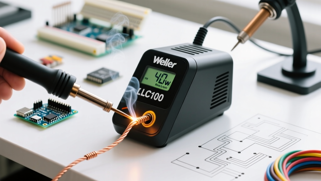
Transitioning to an induction soldering iron requires an upfront investment in the RF generator and the proprietary tip ecosystem. As of 2026, a flagship Metcal MX-520 station retails for approximately $795, while highly capable alternatives like the Quick 206H or Hakko FX-205 can be found in the $400 to $650 range. Individual OEM induction tips typically cost between $35 and $45 each.
While the per-tip cost is higher than standard resistive tips, the operational lifespan of an induction tip is significantly longer. Because the tip never exceeds its engineered Curie temperature, the iron plating does not suffer the micro-fractures and rapid oxidation associated with the thermal overshoot of resistive heaters. For high-volume production environments and serious DIY labs tackling complex multi-layer PCBs, the induction soldering iron remains the undisputed champion of thermal management and joint reliability.