
The Analog Advantage: Mastering the Weller WLC100
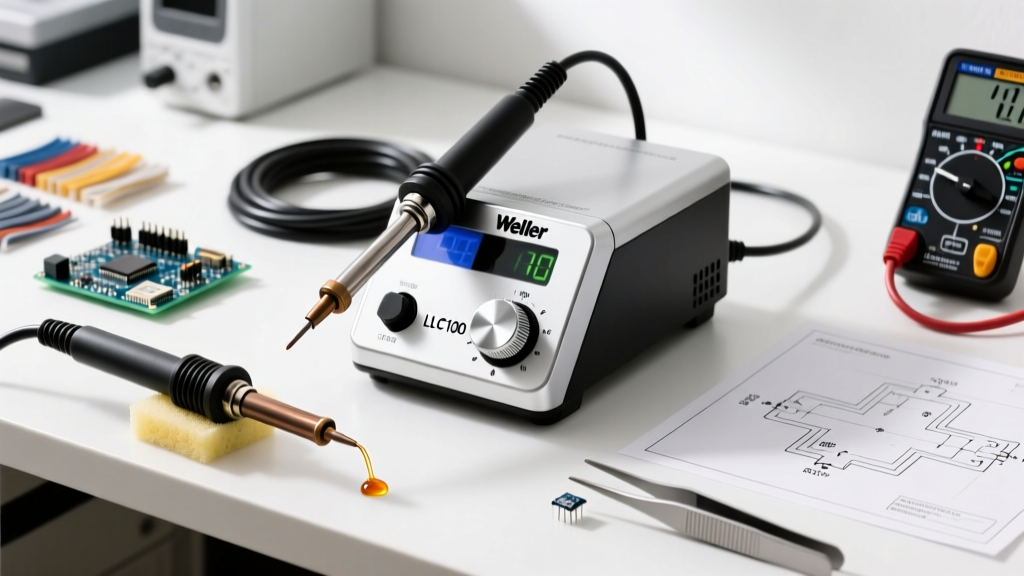
In an era dominated by digital readouts and PID-controlled ceramic heaters, the Weller WLC100 soldering station remains a ubiquitous workhorse on both hobbyist benches and professional repair desks. Priced affordably (typically between $55 and $70 in 2026), this 40-watt analog variable-temperature station offers a unique tactile feedback loop that digital stations often mask. However, because the WLC100 relies on a triac-based phase-angle controller and an analog dial rather than a digital thermocouple readout, mastering it requires a deep understanding of thermal mass, tip geometry, and manual calibration.
This comprehensive technique guide moves beyond the basic manual. We will dissect the thermal architecture of the WLC100, map its notoriously vague dial to actual temperatures, and outline advanced soldering techniques that comply with NASA-STD-8739.3 workmanship requirements for through-hole and surface-mount assemblies.
Understanding the WLC100's Thermal Architecture
The Weller WLC100 operates using the WPB40 40-watt heating element. Unlike modern T12 or T245 cartridge tips where the heater and sensor are integrated directly behind the tip's working face, the WLC100 uses a ceramic heater with a separate sensor sleeve. This creates a slight thermal lag—typically 2 to 4 seconds—between the moment the tip experiences a heat draw and the moment the analog sensor triggers the triac to deliver more power.
Expert Insight: The WLC100 is ESD-safe and grounded via a 3-prong plug. However, if your facility's wiring lacks a true earth ground, the AC leakage from the 40W element can couple into sensitive CMOS or MOSFET gates during contact. Always verify bench grounding with a multimeter before working on live or sensitive logic boards.
Because of this thermal lag, the 'drag soldering' technique often used on high-wattage digital stations will result in cold, disturbed joints on the WLC100. Instead, operators must utilize a 'park and feed' method, allowing the analog sensor time to detect the temperature drop and engage the heating cycle.
Dial Calibration and Temperature Mapping
The most common frustration with the WLC100 is the painted 1-10 dial on the chassis. These numbers do not correspond to exact wattages or specific degrees; they represent arbitrary voltage thresholds sent to the triac. Furthermore, internal potentiometer drift can cause two identical WLC100 units to output different temperatures at the same dial setting. Below is an empirically tested mapping using a K-type thermocouple embedded in a test joint, utilizing standard 63/37 eutectic solder.
| Dial Setting | Approx. Tip Temp (Idle) | Thermal Recovery | Optimal Application |
|---|---|---|---|
| 2 - 3 | 450°F (232°C) | Slow | Fine-pitch SMD (0603/0402), heat-shrink tubing |
| 4 - 5 | 600°F (315°C) | Moderate | Standard through-hole, 63/37 Leaded, DIP ICs |
| 6 - 7 | 700°F (371°C) | Fast | Large terminals, ground planes, SAC305 Lead-Free |
| 8 - 10 | 850°F+ (454°C+) | Immediate | Heavy gauge wire tinning, large copper pours (Use with extreme caution) |
Note: Operating the WLC100 continuously above setting 7 will drastically accelerate tip oxidation and shorten the lifespan of the WPB40 ceramic element.
EC-Series Tip Selection Matrix
The WLC100 utilizes the legendary Weller EC-series screw-on tips. Selecting the correct tip is paramount; a tip with insufficient thermal mass will cause the analog controller to max out its duty cycle without melting the solder, while a tip with excessive mass risks lifting delicate PCB pads.
- ETO (1/8" Screwdriver): The undisputed king of general-purpose work. The flat blade provides excellent surface area for thermal transfer on 0.1" header pins and 0805 SMD pads. Keep this tip on your station for 80% of your tasks.
- ETP (1/4" Heavy Chisel): Essential for tinning 14 AWG to 10 AWG silicone wire and soldering large RC servo connectors. The massive thermal mass compensates for the WLC100's 40W limit by acting as a thermal battery.
- ETC (1/32" Conical): Generally avoid this tip. While marketed for precision work, the conical shape offers terrible thermal transfer characteristics. By the time the tiny point heats the joint, the upper shaft is overheating, leading to premature flux burn-off and dry joints.
- ETS (1/64" Micro Conical): Reserved strictly for 0402 components and micro-soldering under a microscope. Requires setting the dial to 3 and using high-quality, no-clean flux.
The 3-Second Thermal Transfer Technique
To achieve joints that meet the stringent wetting and fillet requirements outlined in IPC J-STD-001, WLC100 operators must adopt a deliberate pacing technique. Because the analog sensor requires a moment to react to thermal draw, rushing the joint guarantees a cold solder connection.
- Prep and Flux: Clean the tip on a dry brass wire sponge (never a wet sponge, which causes thermal shock to the ceramic element). Apply external flux to the PCB pad and component lead.
- The Anchor (0.0s - 1.5s): Place the tinned ETO tip so it simultaneously touches both the PCB pad and the component lead. Hold perfectly still. You will feel a slight 'tack' as the flux activates and the pre-tin flows.
- The Feed (1.5s - 3.0s): Introduce your 63/37 solder wire to the opposite side of the joint, not directly to the iron tip. The heat must travel through the copper and the lead to melt the solder. When the solder flashes and flows into a concave fillet, remove the solder wire first, then the iron.
- The Cool Down: Do not blow on the joint or move the component. The analog nature of the WLC100 means the joint was heated thoroughly; moving it before the eutectic alloy solidifies (approx. 2 seconds) will cause a disturbed, grainy joint.
Troubleshooting Common WLC100 Failure Modes
Despite its rugged reputation, the WLC100 has specific failure modes that mimic a 'broken' heating element. Before ordering replacement parts, diagnose the following:
1. Dial Drift and Inconsistent Heat
If your station requires constant dial adjustments to maintain a stable temperature, the internal 10k potentiometer is likely suffering from carbon tracking or oxidation. The Fix: Unplug the station, open the 4-screw chassis, and spray a small amount of DeoxIT D5 contact cleaner into the potentiometer slots. Rotate the dial back and forth 20 times to scrub the internal contacts. This resolves 90% of 'erratic heating' complaints.
2. Wand Connector Oxidation
The wand connects to the base via a multi-pin circular DIN-style connector. Over time, the pins oxidize, increasing resistance and causing the base to misread the thermocouple voltage. The Fix: Unplug the wand, inspect the pins for green/black corrosion, and clean them with a fiberglass scratch pen or isopropyl alcohol. Ensure the locking collar is tightened securely to prevent micro-disconnects during use.
3. Tip Seizure and Galling
Leaving the EC-series tip locking nut overtightened while the station is hot causes differential thermal expansion, effectively welding the nut to the barrel. The Fix: Always loosen the locking nut slightly while the station is still warm when changing tips. If seized, apply penetrating oil and use a specialized EC-series slotted removal tool—never use pliers, which will crush the fragile ceramic heater sleeve.
Maintenance: Swapping the WPB40 Element
The WPB40 heating element is a consumable. If your iron takes more than 45 seconds to reach operating temperature on setting 5, or if the indicator light stays solidly on without pulsing, the element has likely failed. Replacing it costs roughly $15 and takes 10 minutes.
- Unplug the station and allow the wand to cool completely to room temperature.
- Unscrew the EC tip locking nut and remove the old tip and ceramic sensor sleeve.
- Using a small flathead screwdriver, gently pry the old WPB40 element out of the wand barrel. Note the orientation of the two heater wires and the single, thinner sensor wire.
- Slide the new WPB40 element into the barrel. Ensure the sensor wire aligns perfectly with the center channel; bending this wire will cause immediate open-circuit failure.
- Re-seat the ceramic sleeve and hand-tighten the locking nut. Power on and test at dial setting 4.
Final Verdict on the WLC100 in 2026
While high-frequency induction stations and smart-cartridge irons offer superior thermal recovery for heavy ground-plane work, the Weller WLC100 remains an unmatched value for standard electronics assembly, wire harnessing, and DIY prototyping. By respecting its analog thermal lag, utilizing the correct EC-series tip geometry, and maintaining the internal potentiometer, operators can extract professional, IPC-compliant results from this classic 40-watt station for decades. For further reading on tool maintenance and bench setup, refer to the Weller Tools Official Documentation library.