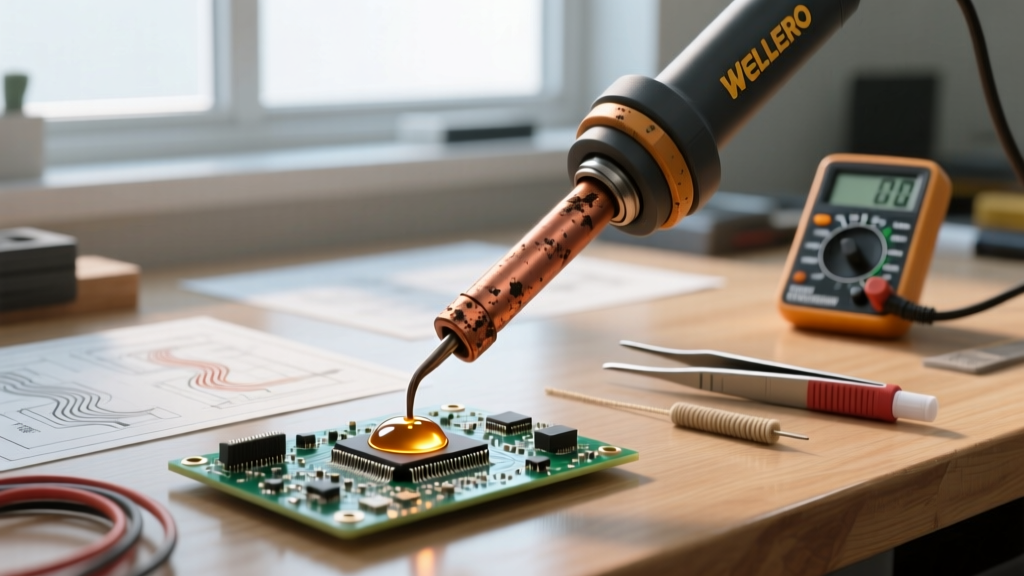

The Hidden Cost of Diverse Soldering Iron Uses in Electronics
When professionals and hobbyists evaluate the broad spectrum of soldering iron uses in electronics, they often focus on technique rather than tool degradation. However, the physical demands of soldering a delicate 0402 surface-mount resistor are vastly different from sinking heat into a 10-layer PCB ground plane. Each specific application stresses the heating element, thermocouple, and iron-plated copper tip in unique ways. In 2026, with the industry's near-total shift to aggressive lead-free alloys like SAC305 (Sn96.5/Ag3.0/Cu0.5), understanding how your specific use-case drives wear and tear is no longer optional—it is critical for maintaining reliable thermal transfer and avoiding catastrophic pad lift-off.
Use-Case Failure Matrix: Diagnosing Tip and Core Degradation
Different soldering iron uses in electronics trigger distinct failure modes. Below is a diagnostic matrix mapping common electronic soldering applications to their primary mechanical and thermal stresses.
| Electronic Application | Typical Temp Range | Primary Failure Mode | Hardware Most at Risk |
|---|---|---|---|
| SMD / Micro-Soldering (0402 to QFN) | 300°C - 320°C | Micro-abrasions from frequent wiping; flux carbonization | Tip iron plating, fine-point shafts |
| Through-Hole & Heavy Ground Planes | 360°C - 400°C | Thermal fatigue, core oxidation, thermal sag | Ceramic heaters, thermocouple joints |
| Desoldering & Rework (BGA/QFP) | 350°C - 380°C | Mechanical bending, aggressive flux corrosion | Tip shaft alignment, sensor wiring |
Troubleshooting Thermal Recovery Issues by Application
A soldering iron that reads 350°C on the display but fails to melt solder on a large copper pour is suffering from thermal sag. Troubleshooting this requires looking at the specific architecture of your station.
1. High-Mass Through-Hole and Ground Planes
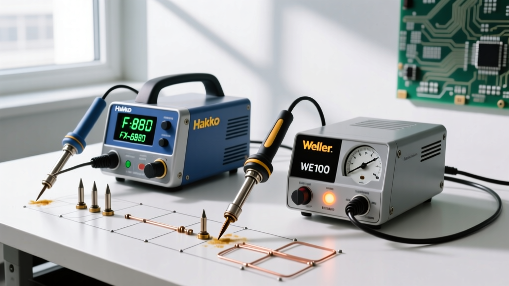
When your primary soldering iron use in electronics involves high-mass components (like TO-220 voltage regulators or large electrolytic capacitors), the tool must dump joules of heat rapidly. If you are using a standard station like the Hakko FX-888D (retailing around $115) with a T18-D24 chisel tip, you may experience severe thermal drop-off. The FX-888D uses a separate ceramic heating rod that slides into the hollow back of the T18 tip. Over time, microscopic air gaps form between the ceramic rod and the tip's inner wall due to thermal expansion and contraction. This air gap acts as an insulator, destroying thermal recovery.
The Fix: Remove the tip and inspect the ceramic rod. If it is blackened with oxidized flux, clean it gently with isopropyl alcohol and a lint-free swab. Never use abrasives on the ceramic sensor. If the station throws an H-E (Heater Error) on the digital display, the ceramic rod has likely cracked from mechanical shock—a common failure when users tap the iron against the holder to clear heavy ground plane solder.
2. Delicate SMD and Micro-BGA Rework
Conversely, micro-soldering requires lower temperatures but demands absolute tip integrity. A pitted or oxidized micro-pencil tip (like the Weller RT1) will cause solder to ball up and refuse to wet the pad, leading to cold joints. Modern smart irons like the Pine64 Pinecil V2 (approx. $26) excel here because their thermocouple is positioned at the extreme front of the tip, providing near-instantaneous thermal feedback. However, if you are powering the Pinecil V2 via a standard 45W USB-C PD charger, it will lack the wattage overhead to sustain heat during prolonged SMD drag-soldering sessions. Always pair smart irons with a 65W or 100W GaN charger to ensure the firmware can pulse maximum current during thermal drops.
Advanced Diagnostics: Testing the Heating Element
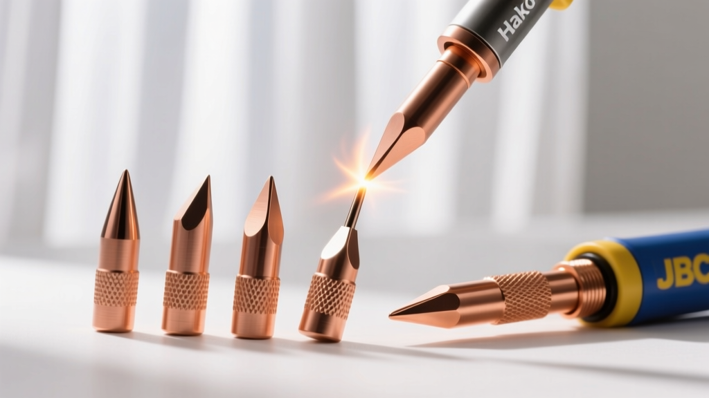
Before discarding a malfunctioning soldering station, use a digital multimeter to test the heating element and sensor circuit. This is especially vital for high-end cartridge systems like the JBC CD-2BQE (approx. $450), which uses C245 tips where the heater, sensor, and tip are a single integrated unit costing upwards of $55 per replacement.
- Power Down and Cool: Unplug the station and let the tip reach room temperature (20°C - 25°C).
- Set Multimeter to Ohms (Ω): Use the lowest resistance range.
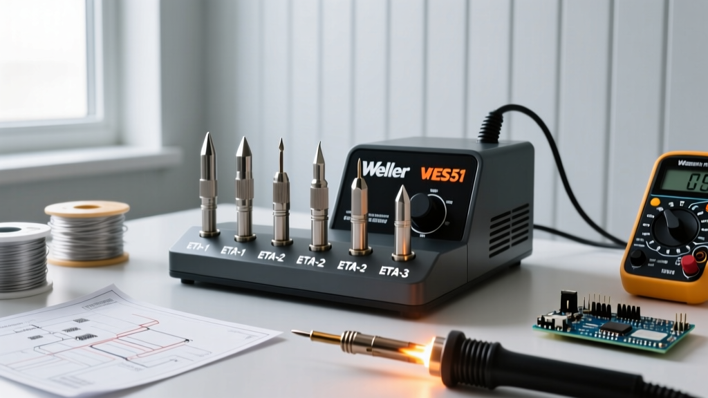
- Probe the Contacts: For a standard Weller ETA or RT series tip, place probes on the heater pins. A healthy heating element typically reads between 2.0Ω and 4.5Ω cold. An infinite reading (OL) indicates a broken internal heating wire, requiring a tip replacement.
- Check the Sensor: Probe the thermocouple pins. You should see a very low resistance (usually under 1Ω). If the sensor reads open, the station will default to maximum heat or shut down entirely to prevent a thermal runaway.
Expert Insight: According to the workmanship standards outlined by NASA's soldering guidelines, a soldering iron must maintain its set temperature within ±5°C during the actual soldering operation. If your multimeter confirms the element is intact but your iron still fails to wet pads, the issue is almost certainly tip oxidation or severe iron plating dissolution, not the station's electronics.
The Chemistry of Tip Destruction: SAC305 vs. Leaded Alloys
You cannot troubleshoot modern soldering iron uses in electronics without addressing solder chemistry. The industry-standard lead-free alloy, SAC305, melts at roughly 217°C–220°C. However, to achieve proper wetting and flow on multi-layer boards, operators routinely push tip temperatures to 380°C. At these elevated temperatures, the tin (Sn) in the SAC305 alloy aggressively attacks the iron (Fe) plating on the tip, dissolving it into the solder pool. This phenomenon, known as tip pitting, exposes the underlying copper core, which rapidly oxidizes and renders the tip useless.
As noted in comprehensive guides like the Adafruit Guide to Excellent Soldering, using a damp cellulose sponge to wipe lead-free solder off a hot tip causes rapid thermal shock, micro-fracturing the iron plating and accelerating this chemical dissolution.
Preventative Maintenance Protocols by Use-Case
To maximize the lifespan of your equipment, implement these strict maintenance routines tailored to your specific electronic soldering applications.
For SMD and Precision Work
- Ditch the Sponge: Replace damp sponges with dry brass wool (e.g., Hakko 599B). Brass is softer than the iron plating but harder than the oxidized solder, removing crust without inducing thermal shock.
- Lower Idle Temperatures: Utilize the sleep/standby function on your station. Dropping the tip to 150°C when not actively soldering reduces oxidation rates by over 70%.
- Flux Management: Use no-clean or RMA (Rosin Mildly Activated) fluxes. Highly activated (RA) fluxes leave corrosive residues that eat through tip plating if not cleaned off the shaft with a fiberglass scratch pen.
For Heavy Through-Hole and Desoldering
- Use Sacrificial Solder: When desoldering large connectors, add fresh, high-quality leaded solder (Sn63/Pb37) to the joint first. This dilutes the aggressive lead-free alloy and lowers the overall melting point, allowing you to reduce your iron's temperature setting by 30°C–40°C, saving the tip.
- Tip Tinning Before Shutdown: Never turn off your station with a bare tip. Melt a large blob of rosin-core solder over the entire working surface of the tip to create an airtight seal against oxygen as it cools.
- Rescue Dead Tips: If a tip becomes completely black and refuses to accept solder, do not scrape it with a knife. Submerge the hot tip into a commercial tip tinner (a mixture of phosphoric acid and solder powder) for 3–5 seconds, then immediately wipe it on brass wool and apply fresh solder.
Final Thoughts on Tool Longevity
Mastering the diverse soldering iron uses in electronics requires more than just a steady hand; it demands an understanding of thermal dynamics and metallurgical wear. Whether you are dragging a micro-pencil across a 0.5mm pitch QFP or driving a massive bevel tip into a copper pour, matching your maintenance routine to your specific application will save you hundreds of dollars in replacement tips and prevent catastrophic damage to expensive PCBs. For further reading on industry-standard soldering techniques and joint inspection, refer to the SparkFun soldering tutorials and always consult your station manufacturer's specific thermal profiles.