
The 'Universal' 5-Pin Trap: Why Physical Fit Does Not Mean Electrical Compatibility
In the electronics repair and DIY landscape of 2026, the market is flooded with both premium soldering stations and budget-friendly clones. A massive point of confusion for technicians and hobbyists alike is the ubiquitous 5-pin connector—typically a 5-pin DIN or a 5-pin aviation (GX16) plug. Because these physical connectors are standardized across dozens of brands, it is a common and catastrophic mistake to assume that a 5-pin soldering iron wiring diagram is universal. It is not.
Plugging a Hakko-style iron into a Weller station, or a generic Yihua iron into a Hakko clone, will almost always result in immediate electrical failure. The physical pin spacing is identical, but the internal wiring diagrams, sensor types, and heater resistances are drastically different. This guide provides a deep-dive tool comparison of the 5-pin wiring architectures used by the industry's top brands, equipping you with the exact data needed to repair, rewire, or safely upgrade your soldering equipment.
Deconstructing the 5-Pin Soldering Iron Architecture
Before comparing specific brands, we must understand why five pins are required for a standard analog or digitally controlled soldering station. Unlike modern T12 or C245 cartridges that integrate the heater and thermocouple into a single series circuit (requiring only 2 or 3 pins), traditional station irons separate these systems for isolated feedback loops.
- Pins 1 & 2 (Heater Circuit): Deliver 24V AC from the station's step-down transformer to the ceramic or nichrome heating element.
- Pins 3 & 4 (Sensor Circuit): Carry the low-voltage millivolt signal from the tip's thermocouple or RTD back to the station's operational amplifier (op-amp) for closed-loop temperature regulation.
- Pin 5 (Earth Ground): Connects the metal shaft and soldering tip directly to the facility's earth ground, ensuring static dissipation and ESD safety.
Weller WES51 / WE1010 (PES51) 5-Pin Wiring Diagram
The Weller WES51 (and its modern digital successor, the WE1010) uses the PES51 or PE1000 soldering pencils. These connect to the base station via a 5-pin DIN plug. Weller's architecture is highly specific and relies on a proprietary sensor curve.
Weller 5-Pin DIN Pinout (Station Receptacle)
- Pin 1: Heater (+)
- Pin 2: Sensor (+)
- Pin 3: Heater (-)
- Pin 4: Earth Ground (Shield)
- Pin 5: Sensor (-)
Technical Specifications: The Weller PES51 heater element typically measures around 9.0 to 9.5 ohms at room temperature. The sensor is not a standard K-type thermocouple; it is a proprietary RTD/thermocouple hybrid that reads approximately 2.0 ohms. The station's control board utilizes a specialized comparator circuit calibrated specifically to this 9-ohm/2-ohm ratio. According to Weller Tools Official Support, attempting to use third-party elements that deviate from these resistance values will cause severe temperature overshoot and premature tip degradation.
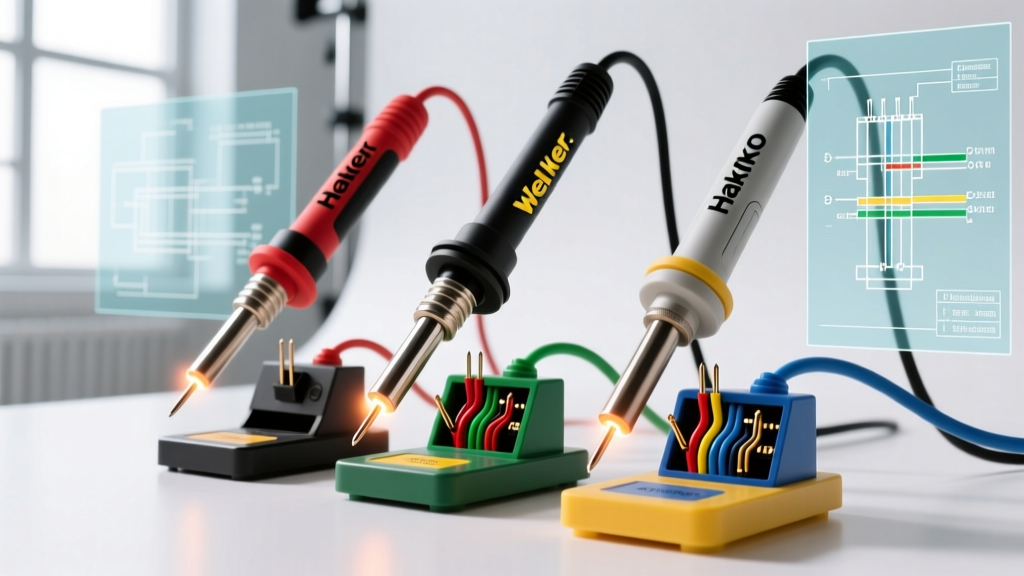
Hakko 936 / FX-888D (A1322/A1323) 5-Pin Wiring Diagram
The Hakko 936 (analog) and FX-888D (digital) utilize the A1322 or A1323 heating elements. While the FX-888D uses a proprietary 4-pin/5-pin hybrid connector in some regions, the classic 936 and the vast majority of global clones (like the Yihua 936) use a standard 5-pin DIN or 5-pin aviation plug. Hakko's wiring diagram is fundamentally incompatible with Weller's.
Hakko / Generic 936 5-Pin DIN Pinout
- Pin 1: Heater (White wire)
- Pin 2: Heater (Blue wire)
- Pin 3: Sensor (Red wire)
- Pin 4: Sensor (Yellow wire)
- Pin 5: Earth Ground (Green wire)
Technical Specifications: The Hakko A1322 heater resistance is significantly lower than Weller's, typically measuring between 4.0 and 6.0 ohms. The sensor is a true K-type thermocouple, reading roughly 1.0 to 1.5 ohms. Because the heater draws nearly double the current of a Weller element at the same 24V AC input, the TRIAC (usually a BTA08-600B) on a Hakko control board is heat-sinked differently. For exact element replacements and safety tolerances, technicians should always consult the Hakko USA Support Portal before attempting board-level repairs.
Tool Comparison Matrix: 5-Pin Station Architectures
The table below highlights the critical electrical differences between the three most common 5-pin soldering iron ecosystems on the market in 2026.
| Feature | Weller WES51 / WE1010 | Hakko 936 / FX-888D | Generic Yihua 927 / 858D |
|---|---|---|---|
| Connector Type | 5-Pin DIN (Locking) | 5-Pin DIN / Aviation | 5-Pin Aviation (GX16) |
| Heater Resistance | ~9.0 Ω | ~4.5 Ω | ~5.0 - 8.0 Ω (Varies) |
| Sensor Type | Proprietary RTD Hybrid | K-Type Thermocouple | K-Type Thermocouple |
| Sensor Resistance | ~2.0 Ω | ~1.2 Ω | ~1.0 - 2.0 Ω |
| Control IC | Custom Weller ASIC / LM358 | HA17358 / LM358P | LM358P / Generic Op-Amp |
| Avg. Station Price (2026) | $135 - $160 | $90 - $115 | $25 - $40 |
Fatal Miswiring Failure Modes: What Happens When You Mix Brands?
WARNING: Never force a 5-pin iron from one brand into the station of another, even if the plug slides in perfectly. The resulting electrical mismatch will destroy solid-state components in milliseconds.
Scenario A: Plugging a Hakko Iron into a Weller Station
Because the Hakko heater is ~4.5 ohms and the Weller station expects ~9.0 ohms, the Hakko iron will draw excessive current. The Weller station's TRIAC will overheat rapidly. More critically, the pinout mismatch means the Weller station will send 24V AC directly into the Hakko's delicate K-type thermocouple pins. This 24V surge travels straight back into the negative feedback loop of the station's LM358 op-amp, instantly vaporizing the silicon junction and often taking the optocoupler with it.
Scenario B: Plugging a Weller Iron into a Hakko/Clone Station
The Hakko station expects a low-resistance heater. When it encounters the Weller's 9-ohm heater, the control loop assumes the iron is cold and keeps the TRIAC locked in the 'ON' position for extended duty cycles. While this might not instantly blow a component, it will cause the Weller's internal thermal fuse to trip or the heating element to burn out due to prolonged maximum-voltage saturation.
Step-by-Step Multimeter Verification for Unmarked 5-Pin Irons
If you are repairing a station or replacing a melted aviation plug on a generic iron, never trust the wire colors. Budget manufacturers frequently change wire color codes between production batches. Use a digital multimeter (DMM) to map the 5-pin wiring diagram organically.
- Set your DMM to Continuity/Resistance (Ohms).
- Identify Earth Ground (Pin 5): Place one probe on the metal soldering tip or the metal shaft of the iron. Touch the other probe to each of the 5 pins. The pin that reads 0.0 to 0.5 ohms is your Earth Ground. Mark it.
- Identify the Heater Circuit: Remove the probe from the tip. Measure the resistance between all remaining pin combinations. The pair that reads between 4.0 and 10.0 ohms is your Heater circuit. Mark these two pins.
- Identify the Sensor Circuit: The remaining two pins are your sensor. Measure them; they should read very low, typically 1.0 to 2.5 ohms (the resistance of the thermocouple wire and junction).
- Determine Sensor Polarity (If Required): Most analog AC stations do not care about thermocouple polarity (Pins 3 and 4 can be swapped). However, if you are wiring a modern digital PID controller, heat the tip slightly with a heat gun and monitor the millivolt (mV) output on the sensor pins to determine positive and negative orientation.
ESD Safety and IPC Compliance: The Importance of Pin 5
In the rush to repair a broken cable, many hobbyists ignore Pin 5 (Earth Ground), assuming the iron will heat up fine without it. While the iron will function, operating an ungrounded soldering iron violates the IPC J-STD-001 Requirements for Soldered Electrical and Electronic Assemblies.
Without Pin 5 connected, the soldering tip acts as an antenna, accumulating stray electromagnetic interference and static charge. When you touch a sensitive component—like the GPIO pins of an ESP32 microcontroller or the gate of a MOSFET—that static discharges through the silicon, causing latent or immediate electrostatic discharge (ESD) failure. Always ensure Pin 5 is soldered with high-quality 63/37 rosin-core wire and routed to a verified earth-grounded terminal on your station's transformer chassis.
Frequently Asked Questions (FAQ)
Can I rewire a 5-pin aviation plug to fit a Hakko DIN receptacle?
Yes, but you must physically cut off the aviation plug and solder a 5-pin DIN plug. You must follow the Hakko pinout diagram exactly (Heater to Pins 1/2, Sensor to Pins 3/4, Ground to Pin 5) and verify with a multimeter before plugging it into the station.
Why does my generic 5-pin iron spark when I plug it in?
A small spark is normal if the station is powered on while connecting, as the transformer's secondary winding charges the iron's internal capacitor. However, a loud pop or a blown station fuse indicates a short circuit between the heater and sensor pins, usually caused by melted internal ceramic insulation near the tip.
Are T12 irons compatible with 5-pin stations?
No. T12 cartridges integrate the heater and sensor in a single series loop requiring only 2 or 3 pins. They cannot be wired to a standard 5-pin analog station without a specialized active adapter board that converts the DC/AC signals.