
The Enduring Legacy of the Weller WES51 in 2026
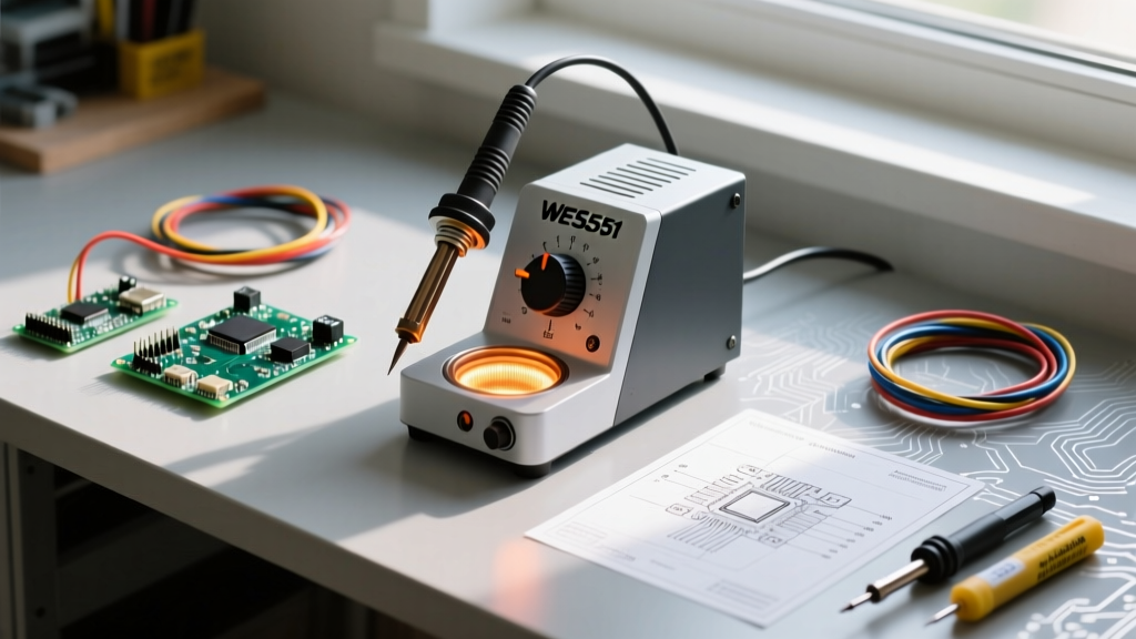
In an era dominated by digital touchscreens and Bluetooth-enabled soldering profiles, the Weller WES51 analog soldering station remains a paradox. While Apex Tool Group has long since shifted its primary manufacturing focus to the digital WE1010NA and WT series, the WES51 continues to command immense respect in MRO (Maintenance, Repair, and Operations) facilities, educational labs, and the workbenches of analog purists. Why? Because its zero-crossing analog power delivery and unmatched mechanical repairability offer distinct advantages that modern PWM (Pulse Width Modulation) stations simply cannot replicate.
As of 2026, sourcing a brand-new WES51 is nearly impossible without tapping into specialized New Old Stock (NOS) MRO liquidators, with refurbished units typically trading between $130 and $175. If you have inherited, purchased refurbished, or are maintaining a fleet of these legendary analog workhorses, this expert guide will walk you through advanced calibration, PES51 handpiece diagnostics, and the critical nuances of analog thermal recovery.
The Analog Advantage: Zero-Crossing vs. PWM
To truly master the Weller WES51 analog soldering station, you must understand its power delivery topology. Modern budget digital stations use high-frequency PWM to regulate temperature. While efficient, rapid PWM switching can generate broadband electromagnetic interference (EMI). When debugging high-impedance audio preamps, sensitive RF circuits, or precision sensor arrays, this EMI can inject noise into your oscilloscope readings or cause erratic behavior in unshielded microcontrollers.
The WES51 utilizes a heavy 50VA toroidal transformer paired with a zero-crossing solid-state relay (triac). Power is delivered to the PES51 heater in full, synchronized AC sine-wave packets. This results in a remarkably clean electrical environment. According to guidelines discussed in the NASA Electronic Parts and Packaging (NEPP) Program regarding workmanship and ESD/EMI control during assembly, minimizing high-frequency noise at the tool level is a critical, often overlooked variable in high-reliability aerospace soldering.
Calibration Protocol: Dial Tracking and Internal Trim
The front-panel temperature dial on the WES51 is a 10k linear potentiometer. Over a decade of mechanical rotation, the internal carbon track develops micro-abrasions, leading to 'dead spots' where the station may drop temperature or surge unpredictably. If your dial feels electrically 'scratchy' or the temperature swings wildly without adjusting the knob, the potentiometer must be replaced.
However, if the dial is smooth but the tip temperature does not match the dial indicator, you must perform an internal offset calibration.
Step-by-Step Internal Calibration
- Preparation: Unplug the station. Remove the four Torx/Phillips screws on the chassis and slide off the metal cover.
- Locate the Trim Pot: Identify the multi-turn blue or white calibration potentiometer on the main PCB (usually labeled 'CAL' or located near the op-amp circuit).
- Thermocouple Setup: Plug in the station and insert an ETA (1/32" chisel) tip. Bind a K-type thermocouple directly to the working face of the tip using high-temperature Kapton tape and a dab of thermal paste to ensure accurate surface reading.
- Adjustment: Set the front dial exactly to 350°C (662°F). Using a ceramic adjustment tool, turn the internal trim pot until your multimeter reads exactly 350°C at the thermocouple.
- Verification: Allow the station to cycle off and back on three times to verify thermal stability.
Dial Setting vs. Expected Tip Temperature Matrix
When calibrating or verifying your station, use this reference matrix based on standard ETA series tips in a still-air environment at 22°C ambient.
| Dial Setting (°C) | Expected Tip Temp (°C) | Acceptable Drift Margin | Recommended Application |
|---|---|---|---|
| 260°C | 255°C - 265°C | ± 5°C | Lead-free 0402 SMD, heat-sensitive ICs |
| 315°C | 310°C - 320°C | ± 5°C | Standard Sn63/Pb37 through-hole |
| 350°C | 345°C - 355°C | ± 5°C | Heavy ground planes, large connectors |
| 425°C | 415°C - 435°C | ± 10°C | Desoldering, heavy gauge wire tinning |
Note: Always calibrate using the specific tip profile you use most frequently. The thermal mass of an ETS (screwdriver) tip will read slightly differently at the surface than an ETA (chisel) tip due to varying distances from the internal heating element.
PES51 Handpiece: Diagnostics and Failure Modes
The PES51 iron is the heart of the WES51 system. It connects via a locking 5-pin DIN connector. The most common failure mode in 2026 is not the heating element itself, but the degradation of the internal PTFE wiring insulation near the grip, leading to intermittent sensor readings. If your WES51 indicator LED flashes rapidly and the iron remains cold, the station's internal logic has detected an open sensor circuit and entered a fail-safe shutoff mode.
5-Pin DIN Connector Diagnostic Pinout
Use a digital multimeter (DMM) to test the PES51 handpiece directly at the connector pins. Disconnect the iron from the station before testing continuity and resistance.
- Pin 1 to Pin 3 (Heater Element): Should read between 9.0Ω and 11.0Ω at room temperature. An 'OL' (Open Loop) reading indicates a snapped internal heater wire, requiring a full PES51 heater/sensor assembly replacement.
- Pin 2 to Pin 3 (Thermocouple Sensor): Should read near 0.0Ω to 2.0Ω. More importantly, set your DMM to millivolts (mV). Heat the tip slightly with a heat gun; you should see a proportional increase in mV output. If it reads 0mV under heat, the sensor is dead.
- Pin 4 (Chassis Ground): Verify continuity between Pin 4 and the metal barrel of the handpiece. This is critical for ESD safety and compliance with IPC J-STD-001 standards for grounded soldering equipment.
- Pin 5: Not Connected (N/C) on standard WES51 configurations.
Sourcing Genuine Parts in a Market Flooded with Counterfeits
Because the WES51 is no longer in primary production, the aftermarket is saturated with counterfeit ETA tips and cloned PES51 heater assemblies. Using counterfeit tips on a WES51 analog soldering station will completely destroy its thermal recovery capabilities.
'An analog station relies entirely on the physical thermal mass and conductivity of the tip to bridge the gap between the sensor's feedback loop and the workpiece. A counterfeit tip with improper copper coring acts as a thermal choke, forcing the analog triac to remain in a continuous 'on' state, eventually burning out the station's internal transformer.'
How to Identify Genuine Weller ETA Tips in 2026
- The Laser Etch Test: Genuine Weller tips feature a deep, precise laser etching of the part number (e.g., 'ETA') and a manufacturing date code. Counterfeits often use shallow ink stamping that flakes off after a single session with rosin flux.
- Weight and Balance: A genuine ETA tip weighs exactly 7.2 grams. Fakes often use thicker, cheaper iron cladding over a smaller copper core, resulting in a heavier tip (often >8.5 grams) that feels unbalanced in the PES51 grip.
- The Plating Line: Look inside the hollow shaft of the tip. Genuine Weller tips have a distinct, clean transition line where the iron cladding stops and the bare copper core begins. Fakes often have messy, uneven plating overspray.
For verified replacements, avoid third-party marketplace vendors. Source your legacy Weller components directly through authorized industrial distributors listed on the Apex Tool Group's Weller Brand Page or established MRO suppliers like Newark or Farnell, who still maintain verified inventory of legacy Weller repair kits and genuine ETA tip multipacks.
Expert Tip Selection for Analog Thermal Recovery
Digital stations use predictive algorithms to push extra wattage into the heater before the tip temperature drops significantly during a solder joint. The WES51 reacts strictly to real-time thermal deficit. Therefore, tip geometry and mass are your primary thermal buffers.
When soldering heavy multi-layer PCB ground planes with the WES51, avoid conical tips (like the ETC). The surface area contact is too small, and the analog station will max out its 50W capacity trying to recover the lost heat, leading to cold joints. Instead, utilize the ETS (1/16" Screwdriver) or the ETK (heavy chisel). The increased surface area ensures efficient thermal transfer, allowing the WES51's analog triac to cycle normally and maintain a stable, IPC-compliant wetting time of 2 to 4 seconds per joint.
Final Thoughts on Maintaining the Analog Standard
The Weller WES51 analog soldering station is not a relic; it is a precision analog instrument. By understanding its zero-crossing topology, rigorously maintaining the PES51 handpiece, and strictly sourcing genuine thermal consumables, you can keep this station performing at the absolute pinnacle of electronics manufacturing standards well into the late 2020s and beyond. Treat the analog dial with respect, calibrate it bi-annually, and it will outlast the digital screens of its modern successors.