
Introduction to Cordless Thermal Management
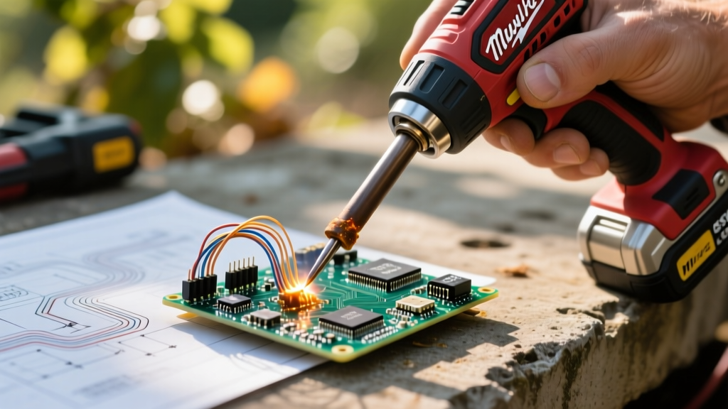
The transition from benchtop AC stations to cordless DC tools has fundamentally changed how electrical technicians, automotive diagnosticians, and off-grid solar installers approach field repairs. At the forefront of this shift is the Milwaukee 48-22-6800 M12 Soldering Iron. While its 30-second heat-up time and 800°F (426°C) maximum temperature are impressive on paper, treating a battery-powered 12V DC iron exactly like a 60W Weller or Hakko AC station is a recipe for cold joints, damaged PCB pads, and depleted batteries. This technique guide dives deep into the specific operational nuances of the M12 Milwaukee soldering iron, providing actionable frameworks for thermal management, tip geometry selection, and heavy-gauge field soldering.
The Physics of 12V DC Heating Elements
To master the M12 Milwaukee soldering iron, you must first understand its power delivery curve. Traditional benchtop stations use AC transformers or high-frequency induction to deliver continuous, regulated wattage. The M12 iron relies on a direct resistive heating element powered by a 12V lithium-ion battery.
Using the formula for electrical power (P = V²/R), the wattage output is intrinsically tied to the battery's voltage. A fully charged M12 REDLITHIUM CP2.0 battery outputs roughly 12.6V, allowing the iron to peak near 75W. However, as the battery depletes and voltage drops to 11.2V under load, the available wattage drops significantly, reducing thermal recovery speed. This means your soldering technique must adapt to the battery's state of charge. You cannot rely on the iron to instantly recover from massive thermal shocks when soldering large ground planes or thick wires; instead, you must use chemical thermal bridges (flux) and strategic pre-heating to compensate for the DC power curve.
Tip Selection Matrix for the M12 Platform
The Milwaukee M12 iron accepts standard 1/4-inch (6.35mm) shank tips, making it cross-compatible with the widely available Hakko 900M series and Milwaukee's proprietary replacements. Selecting the correct tip geometry is critical when operating on limited DC wattage. Conical tips concentrate heat into a tiny surface area, which rapidly drains the tip's thermal mass when it touches a cold wire. For the M12 platform, maximizing surface area contact is mandatory.
| Tip Geometry | Thermal Mass | Best M12 Application | Avoid When |
|---|---|---|---|
| 1/16" Chisel (D-Shaped) | Medium | Through-hole PCB components, 18-22 AWG tinning, general electronics. | Soldering large ground planes or heavy gauge wires. |
| 1/8" Bevel (Angled) | High | Pre-tinning thick wires, dragging solder across multi-pin ICs. | Tight vertical clearances on dense PCBs. |
| Conical (Pointed) | Low | None recommended for M12. | All heavy field work; causes severe voltage sag and cold joints. |
| Wide Blade (Flat) | Very High | XT60/XT90 connectors, 10-12 AWG wire, automotive spade terminals. | Precision SMD work. |
Expert Insight: According to the NASA Workmanship Training Program standards, proper tip wetting and surface area contact are the primary drivers of efficient heat transfer. On a 12V DC iron, using a wide chisel or bevel tip ensures maximum thermal transfer before the battery's BMS (Battery Management System) experiences heavy voltage sag.
Battery Voltage Sag and Thermal Recovery
One of the most common failure modes when using the M12 Milwaukee soldering iron in the field is the 'disturbed joint'—a defect explicitly rejected by the IPC J-STD-001 standard for soldered assemblies. This occurs when the battery voltage sags mid-joint, the iron drops below the solder's liquidus temperature, and the technician moves the wire before the alloy fully solidifies.
To prevent this, implement the Staggered Heat Technique:
- Pre-Tin Both Surfaces: Never attempt to join a bare wire to a bare terminal directly with the iron. Pre-tin the wire and pre-tin the terminal separately while the battery is at peak voltage.
- The 3-Second Rule: When joining pre-tinned surfaces, apply the M12 iron for no more than 3-4 seconds. If the solder does not flow and fuse within this window, remove the iron, let the battery recover for 10 seconds, and reapply.
- Aggressive Fluxing: Use a high-activity, no-clean tacky flux (such as Amtech NC-559 or Chip Quik SMD291). Flux lowers the surface tension of the molten solder and acts as a chemical thermal bridge, compensating for the M12's lower continuous wattage compared to AC stations.
Step-by-Step: Soldering 12 AWG XT60 Connectors in the Field
Soldering 12 AWG silicone wire into an XT60 nylon connector is a notorious challenge for cordless irons. The copper wire acts as a massive heatsink, and the nylon housing melts at roughly 428°F (220°C)—dangerously close to the melting point of lead-free solder. Here is the exact procedure for executing this flawlessly with the M12 Milwaukee iron using 63/37 Sn/Pb eutectic solder (melting point 361°F / 183°C).
- Preparation: Strip exactly 1/4-inch of insulation from the 12 AWG wire. Apply a generous coating of tacky flux to the exposed copper strands.
- Wire Pre-Tinning: Fit the M12 with a Wide Blade or 1/8" Bevel tip. Set the temperature dial to 75% (roughly 650°F). Tin the wire until the solder wicks completely to the insulation edge. Wipe the tip on a damp brass sponge.
- Connector Pre-Tinning: Insert the wire into the XT60 cavity to gauge depth. Remove the wire. Apply flux inside the XT60 solder cup. Insert the tinned tip into the cup for exactly 2 seconds to melt a small pool of solder inside the terminal. Do not heat the nylon housing.
- The Fusion Join: Insert the pre-tinned wire into the pre-tinned XT60 cup. Apply the M12 iron to the side of the metal terminal (avoiding the nylon) for 2 to 3 seconds. The existing solder on both surfaces will instantly reflow and fuse.
- Thermal Lock: Remove the iron and hold the wire perfectly still for 4 seconds while the 63/37 eutectic solder snaps through its plastic phase and solidifies.
Troubleshooting Field Defects on Battery Power
Even with perfect technique, environmental factors and battery degradation can introduce defects. Here is how to diagnose and correct common issues specific to the M12 platform:
1. Grainy or Dull Solder Fillets
Cause: Using SAC305 (Lead-Free) solder on a depleted M12 battery. SAC305 requires 422°F to melt and has a wide 'pasty' range where it is semi-solid. If the 12V battery sags, the iron cannot maintain the necessary thermal envelope, resulting in a disturbed, grainy joint.
Solution: Switch to 63/37 Sn/Pb eutectic solder for all heavy-gauge field repairs. Eutectic solder transitions instantly from liquid to solid, eliminating the pasty phase and forgiving minor voltage sags.
2. Solder Balling and Dewetting
Cause: Oxidation on the tip due to leaving the M12 iron on at maximum temperature without use. The 12V DC element can spike localized tip temperatures rapidly when not transferring heat to a workpiece.
Solution: Utilize the Milwaukee iron's manual lock-off slider aggressively. If you are not actively soldering for more than 30 seconds, power the tool off. Always leave a blob of fresh solder on the tip before powering down to act as a sacrificial oxidation layer.
3. Iron Cuts Out Mid-Solder
Cause: The M12 REDLITHIUM BMS has tripped due to a low-voltage cutoff or thermal overload in the battery pack, often exacerbated by using older, degraded CP2.0 batteries in freezing field conditions.
Solution: Upgrade to the M12 HIGH OUTPUT CP3.0 batteries. The high-output cells feature lower internal resistance, drastically reducing voltage sag under the heavy continuous amp-draw of the soldering iron's heating element, especially in sub-50°F (10°C) outdoor environments.
Final Thoughts on Cordless Soldering
The M12 Milwaukee soldering iron is a highly capable field instrument, provided the operator respects the physics of DC power delivery. By abandoning the 'brute force' heating methods used on infinite-AC benchtop stations and adopting flux-heavy, pre-tinned, and thermally staggered techniques, technicians can achieve IPC-compliant, aerospace-grade solder joints anywhere in the field. Master your tip geometry, manage your battery voltage, and let the chemical properties of eutectic solder do the heavy lifting.