
Understanding Soldering Iron Temperatures: The Baseline
When electronics hobbyists and professionals ask, "how hot is a soldering iron?", the answer depends entirely on the thermal mass of the joint and the specific solder alloy being used. A typical electronics soldering station operates between 250°C and 400°C (482°F to 752°F). However, heavy-duty plumbing irons can exceed 500°C (932°F) to melt high-temperature antimony alloys and overcome the massive heat dissipation of copper pipes.
Running your iron at the wrong temperature is one of the fastest ways to destroy expensive tips and create unreliable, cold solder joints. According to the IPC J-STD-001 standard for soldered electrical assemblies, thermal profiles must be strictly managed to prevent thermal shock to components while ensuring proper intermetallic compound (IMC) formation.
Ideal Temperature Ranges by Solder Alloy
The golden rule of soldering is to set your iron approximately 50°C to 100°C above the melting point of your solder alloy. This delta accounts for the immediate heat loss when the tip contacts the room-temperature PCB pad and component lead.
| Solder Alloy | Melting Point | Recommended Iron Temp | Primary Use Case |
|---|---|---|---|
| Sn63/Pb37 (Leaded) | 183°C (361°F) | 300°C - 330°C | General DIY, prototyping, repair |
| SAC305 (Lead-Free) | 217°C (423°F) | 350°C - 380°C | Commercial manufacturing, RoHS compliance |
| Sn96.5/Ag3/Cu0.5 | 217°C (423°F) | 360°C - 390°C | High-reliability aerospace/medical |
| 95/5 (Sn/Sb Plumbing) | 250°C (482°F) | 400°C - 450°C+ | Copper water lines, HVAC |
Troubleshooting: Why Is My Soldering Iron Not Getting Hot Enough?
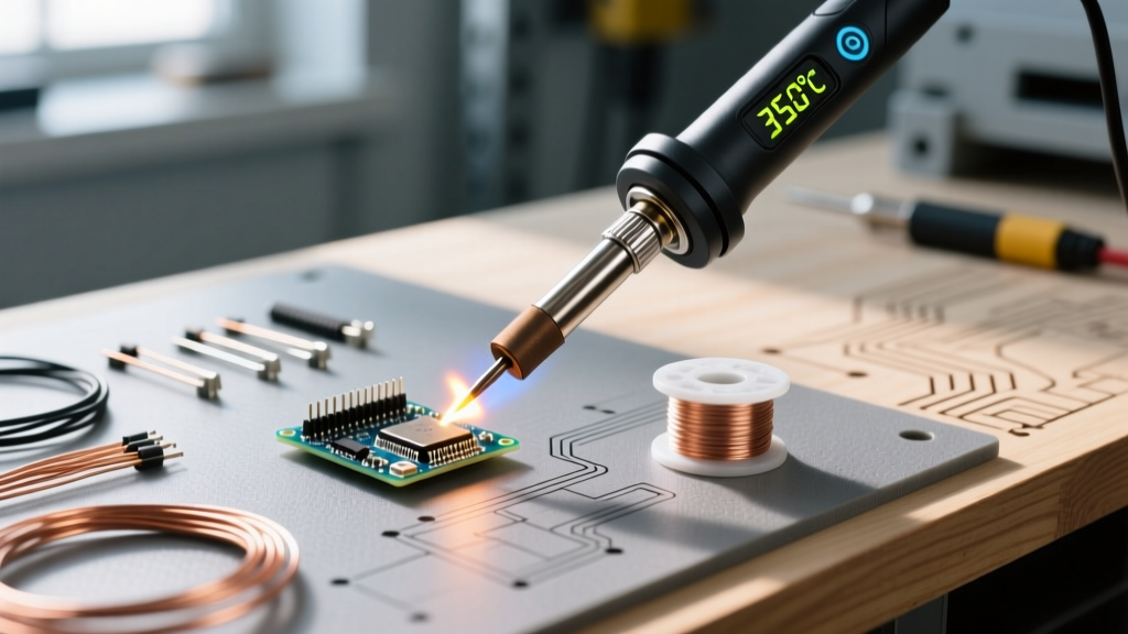
If your station reads 350°C on the digital display but the solder refuses to melt on the pad, you are experiencing a thermal transfer failure or a sensor calibration error. Here is how to diagnose the most common culprits.
1. Severe Tip Oxidation (The Thermal Insulator)
When a copper-core tip is exposed to high heat without a protective layer of flux and solder, the iron plating oxidizes, forming a black, crusty layer of iron oxide. Iron oxide is a thermal insulator. Even if the internal heating element is at 400°C, the surface of the tip might only be 180°C.
- The Fix: Never use sandpaper or a file, which will permanently destroy the iron plating. Use a damp cellulose sponge or a brass wire wool (like the Hakko 599B) while the iron is hot. Apply a generous amount of rosin-core solder or a dedicated tip tinner (like Amtech BC-1) immediately after cleaning to re-tin the surface.
2. Thermal Mass Overload (The Heatsink Effect)
If you are trying to solder a thick 10oz copper ground plane on a 4-layer PCB using a standard 70W station like the Weller WE1010NA, the iron's temperature will plummet the moment it touches the board. The PCB acts as a massive heatsink, drawing heat away faster than the 70W element can replenish it.
- The Fix: Do not simply turn the temperature up to 450°C, which will burn your flux and delaminate the PCB. Instead, use a PCB preheater (such as the Quick 853A) to bring the entire board up to 120°C–150°C before applying the iron. This drastically reduces the thermal delta.
3. Failing Thermocouple or Heater Assembly
In stations like the Hakko FX-888D, the heating element (Part #B2032) contains an integrated thermocouple. If the internal wiring degrades or the harness is pinched, the resistance changes. The station's microcontroller reads this altered resistance and incorrectly assumes the tip is hotter than it actually is, prematurely cutting power to the heater.
- The Fix: Use a digital multimeter to check the resistance of the heater pins at the base station's receptacle. Compare the readings against the manufacturer's service manual. If the sensor pins show an open circuit or out-of-spec resistance, replace the ceramic heater assembly.
Troubleshooting: Overheating and Runaway Temperatures
An iron that won't stop heating is a severe fire hazard and will destroy your tips within minutes. Runaway heat is almost always a failure in the closed-loop feedback system.
Expert Warning: If your soldering iron handle becomes too hot to hold, or if solder instantly vaporizes and pits the tip upon contact, unplug the station immediately. Do not attempt to cool the tip by dunking it in water, as thermal shock will shatter the internal ceramic heating element.
Open Sensor Circuit (The 100% Duty Cycle Failure)
Soldering stations use a PID controller to maintain temperature. The thermocouple sends a millivolt signal back to the base station. If the sensor wire inside the pencil handle breaks (an open circuit), the controller reads 0V. The microcontroller interprets this as the tip being at absolute zero and fires the TRIAC or solid-state relay at a 100% duty cycle, pumping maximum AC voltage into the heater until it glows red hot or melts the handle.
- Diagnostic Step: Unplug the iron. Set your multimeter to measure DC millivolts. Probe the sensor pins on the iron's plug. Gently wiggle the cord near the handle strain relief. If the voltage fluctuates wildly or reads infinite resistance, the internal sensor wire is broken. Replace the pencil assembly.
Shorted TRIAC / Solid State Relay
In older analog stations like the legendary Weller WES51, temperature is controlled by a TRIAC on the main PCB. If the TRIAC fails in a "shorted" state, it bypasses the control circuit entirely, delivering uninterrupted mains voltage to the iron regardless of the dial setting.
- Diagnostic Step: Open the base station enclosure (ensure it is unplugged!). Locate the TRIAC mounted to the heatsink. Use a multimeter in diode/continuity mode to test the Main Terminal 1 (MT1) and Main Terminal 2 (MT2). If it shows continuity in both directions without a gate trigger, the TRIAC is shorted and must be desoldered and replaced.
Preventative Maintenance Protocols
Proper maintenance ensures your heating elements and sensors last for years. Follow these protocols to extend the life of your equipment:
- Always Leave a Solder Blob: Before turning off your station, melt a large bead of rosin-core solder onto the tip. This sacrificial layer will oxidize while the iron cools, protecting the underlying iron plating.
- Utilize Sleep Mode: Modern stations like the JBC CD-2BQE or Hakko FX-951 feature auto-sleep. Leaving an iron at 380°C on a holder for hours accelerates tip erosion exponentially. Ensure sleep mode is enabled to drop the temp to 150°C when idle.
- Annual Calibration: Use a tip thermometer (like the Hakko 191) to verify the actual tip temperature against the digital display. Adjust the internal calibration potentiometer or digital offset if the variance exceeds ±5°C.
Frequently Asked Questions
Can I use a plumbing soldering iron for electronics?
No. Plumbing irons (often 100W to 250W with massive chisel tips) lack the precise temperature control required for PCBs. The extreme thermal mass and high operating temperatures will instantly lift copper pads, scorch FR4 fiberglass, and destroy sensitive silicon dies via thermal runaway.
Why does my lead-free solder joint look dull and grainy?
Lead-free alloys like SAC305 require higher temperatures (around 360°C) and often suffer from poor wetting. If your iron is set too low (e.g., 300°C), the solder won't fully reflow, resulting in a cold, grainy joint. Furthermore, lead-free fluxes burn out faster; you may need to add external liquid flux to achieve a smooth, shiny fillet.
How often should I replace my soldering iron tip?
With proper maintenance and correct temperature settings, a high-quality tip (like those from Weller or JBC) can last for thousands of joints. However, if you notice pitting, visible copper showing through the iron plating, or if solder consistently rolls off the tip, it is time for a replacement. For more on beginner techniques, refer to the SparkFun through-hole soldering guide for foundational best practices.