
Introduction to the Weller WE1010NA Digital Station
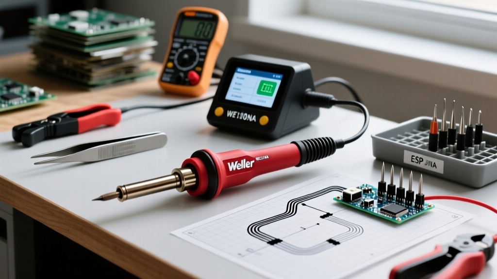
The Weller WE1010NA represents a significant leap from legacy analog stations, offering 70 watts of digital power, precise thermal recovery, and an intuitive LCD interface. As of 2026, retail pricing for the WE1010NA kit typically ranges between $115 and $135, making it a dominant force in both professional repair labs and advanced DIY workbenches. However, transitioning from analog dial-based stations to a fully digital ecosystem requires a nuanced understanding of its menu architecture and thermal management system. This guide provides a comprehensive, step-by-step tutorial on setting up, configuring, and verifying the calibration of your Weller WE1010NA soldering iron to ensure compliance with modern electronics manufacturing standards.
Physical Setup and Cable Management
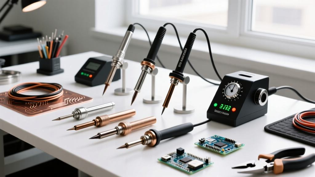
Before applying power, proper physical arrangement of the WEL-1010 power unit and WEP-70 handpiece is critical for longevity and safety. The kit includes the KH27 safety rest and a brass wool sponge. Unlike older models that used a wet cellulose sponge exclusively, the brass wool is superior for lead-free solder maintenance as it does not induce thermal shock on the ETA tip.
- Handpiece Routing: Ensure the silicone-jacketed cable is not wrapped tightly around the station. The internal heater wires and thermocouple leads are susceptible to fatigue failure if bent at sharp angles near the strain relief.
- Rest Positioning: Place the KH27 stand to the right of the unit (or left, if you are left-handed) ensuring the iron rests at a natural downward angle. This prevents molten solder from wicking back up the shaft and degrading the internal heating element connections.
- Brass Wool Prep: Fluff the brass wool slightly before first use. Do not pack it tightly, as this can scrape the delicate iron plating off the ETA tips during cleaning.
Power-On Sequence and Interface Navigation
The WE1010NA utilizes a three-button interface: Up, Down, and Menu/Enter. Upon plugging the unit into a grounded 120V AC outlet and flipping the rear rocker switch, the LCD will illuminate and display the last used temperature.
- Initial Heat-Up: Press the Up or Down arrows to set your target temperature. For standard 63/37 leaded solder, 350°C (662°F) is the optimal baseline. For SAC305 lead-free alloys, bump the target to 370°C (698°F).
- Standby Activation: Place the iron into the KH27 rest. If Auto-Off is enabled, the station will detect the rest state via the internal handpiece sensor and begin the countdown to standby mode.
- Boost Mode: Unlike some competitor stations with a physical 'boost' button, the WE1010NA handles thermal recovery dynamically. When the tip detects a massive heat sink (like a multi-layer ground plane), the digital PID controller automatically pushes the full 70W to the heater core without user intervention.
Advanced Menu Configuration Matrix
To access the deep configuration settings, press and hold the Menu/Enter button for three seconds until the display flashes. Use the arrows to cycle through the parameters, and press Menu/Enter to confirm.
| Menu Code | Function | Recommended Setting | Expert Insight |
|---|---|---|---|
| 1 | Temperature Unit | Celsius (°C) | Most IPC datasheets and solder paste profiles reference Celsius. Standardize your lab to avoid conversion errors. |
| 2 | Auto-Off Timer | 9 Minutes | Setting this between 5-10 minutes preserves tip life by dropping the temp to 200°C when idle, preventing flux carbonization. |
| 3 | Acoustic Buzzer | OFF | Disables the beep when target temp is reached or when standby activates. Highly recommended for shared lab environments. |
| 4 | Temperature Lock | ON (Set PIN) | Crucial for production environments. Prevents operators from exceeding the IPC J-STD-001 thermal limits for sensitive components. |
The Calibration Reality: Debunking the Trim Pot Myth
One of the most common search queries from technicians transitioning from the legendary Weller WES51 analog station is how to access the 'calibration trim pot' on the WE1010NA. Here is the critical E-E-A-T reality: The Weller WE1010NA does not have a user-accessible calibration offset menu or a physical trim potentiometer.
Expert Note: Legacy analog stations required periodic manual calibration via a screw on the back panel to compensate for analog drift. The WE1010NA uses a digital closed-loop system where the thermocouple is embedded directly inside the removable ETA tip. The station reads the raw millivolt output from the tip's thermocouple and applies a factory-programmed digital curve. Therefore, the station itself does not drift out of calibration; the tips do.
If your station reads 350°C but your external thermometer reads 335°C, the station is not 'uncalibrated'—the thermocouple inside your specific ETA tip has degraded due to prolonged thermal stress, or the heater core interface has oxidized. Attempting to 'hack' a calibration offset into the firmware is impossible on the retail NA model. The correct protocol is to verify the tip and replace it if the delta exceeds ±10°C.
Verifying Thermal Accuracy with a Tip Thermometer
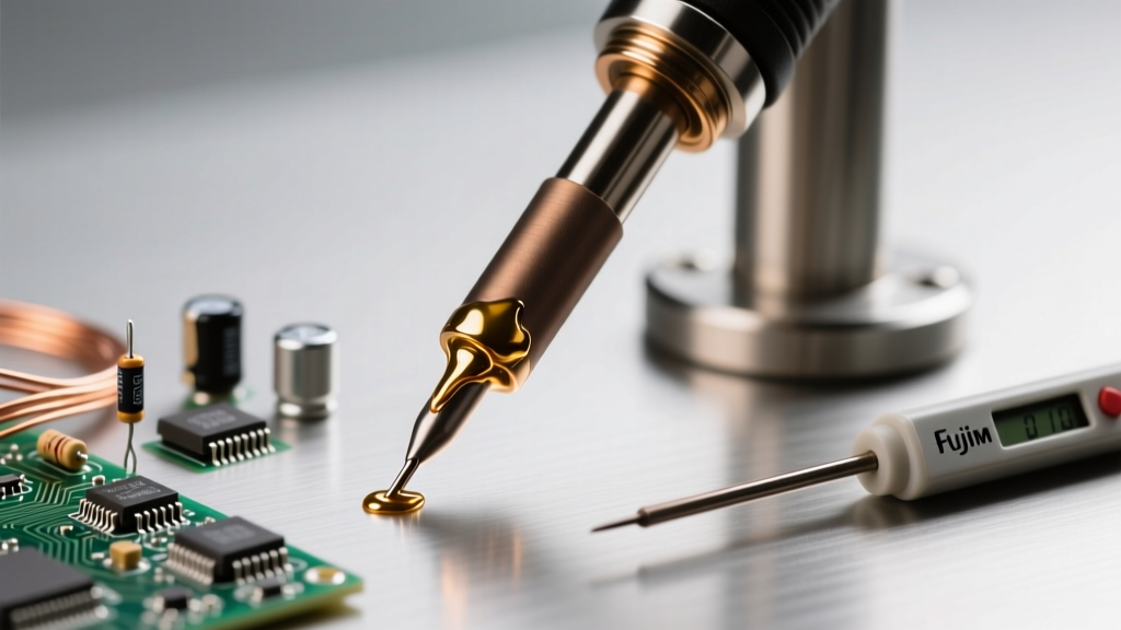
To ensure your setup meets the strict thermal profiling requirements outlined by Weller Tools official documentation and industry standards, you must periodically verify tip temperature using a dedicated tip thermometer (such as the Hakko FG-100 or Weller WSTA1).
- Preparation: Allow the WE1010NA to stabilize at 350°C for at least three minutes. Ensure the tip is clean and freshly tinned.
- Measurement: Apply a small bead of high-temp thermal paste to the tip thermometer's sensor. Press the sensor firmly against the flat working surface of the ETA tip.
- Evaluation: Wait for the thermometer reading to stabilize (usually 10-15 seconds). If the variance is within ±5°C (±9°F), your tip and station are operating perfectly. If the variance exceeds 15°C, discard the tip and test a brand new, factory-sealed ETA tip. If the new tip also reads incorrectly by a wide margin, the internal heater/sensor assembly of the WEP-70 handpiece may be failing.
ETA Tip Selection and Thermal Recovery Profiles
The WE1010NA's 70W heater is highly capable, but its effectiveness is entirely bottlenecked by the thermal mass of the selected tip. Choosing the wrong tip geometry will result in cold solder joints, regardless of the digital temperature readout.
| Tip Series | Geometry | Best Application | Thermal Mass |
|---|---|---|---|
| ETS | Micro / Pencil | 0402 SMD components, fine-pitch ICs, delicate flex PCBs. | Low (Fast heat-up, rapid heat loss on planes) |
| ETA | Standard Chisel | Through-hole resistors, standard wire tinning, general DIY. | Medium (The default all-rounder) |
| ETB | Heavy Chisel | Large terminals, thick gauge wires (14-18 AWG), XT60 connectors. | High (Sustains heat during heavy draw) |
| ETP | Power / Bevel | Multi-layer ground planes, heavy copper pours, plumbing (with caution). | Maximum (Requires full 70W PID engagement) |
Diagnostic Error Codes and Troubleshooting
The digital display on the WE1010NA acts as a diagnostic window into the health of the handpiece. Familiarize yourself with these hardware-level error codes to minimize bench downtime:
- H1 (Open Circuit): The station cannot detect the thermocouple. This usually means the ETA tip is not fully seated in the heater core, the locking nut is loose, or the thermocouple wire inside the tip has snapped. Fix: Reseat the tip and tighten the KH27 locking nut securely.
- H2 (Short Circuit): The sensor wires are shorting together. This is a rare failure mode usually caused by catastrophic physical damage to the handpiece cable or internal heater assembly melting. Fix: Inspect the silicone cable for burns; replace the WEP-70 handpiece if the cable is intact but the error persists.
- H3 (Heater Failure / Overheat): The PID controller detects that the heater is drawing abnormal current or the temperature is rising uncontrollably (a runaway thermal event). Fix: Immediately power off the station. This indicates a failed TRIAC on the main PCB. The WEL-1010 power unit requires professional service or replacement.
Final Thoughts on Digital Soldering Maintenance
Setting up the Weller WE1010NA is not just about plugging it in; it is about configuring the digital parameters to match your specific workflow and understanding the physical realities of embedded thermocouple technology. By properly configuring the Auto-Off timer, utilizing the Temperature Lock for IPC compliance, and relying on tip replacement rather than phantom calibration menus, you ensure that your 70W digital station delivers flawless, repeatable solder joints for years to come. Always remember that a digital readout is only as accurate as the physical tip transferring the heat to your workpiece.