
Why Precision Calibration Matters in 2026
As surface-mount components shrink to 0201 and 01005 imperial sizes, and lead-free solder alloys demand higher thermal profiles, the margin for error in electronics assembly has effectively vanished. A Weller soldering station is an industry benchmark for thermal recovery and durability, but out-of-the-box accuracy can drift due to shipping impacts, ambient temperature variations, or thermocouple degradation. According to the IPC J-STD-001 standard, soldering equipment must maintain temperature tolerances within ±5°C (±9°F) of the set point to prevent cold joints or thermal damage to sensitive ICs.
This comprehensive tutorial will walk you through the physical setup, digital offset calibration, and verification processes for the most popular Weller models on the market today, including the WE1010NA, the high-end WD1001, and the legacy analog WES51.
Phase 1: Physical Setup and the 'Air Gap' Danger
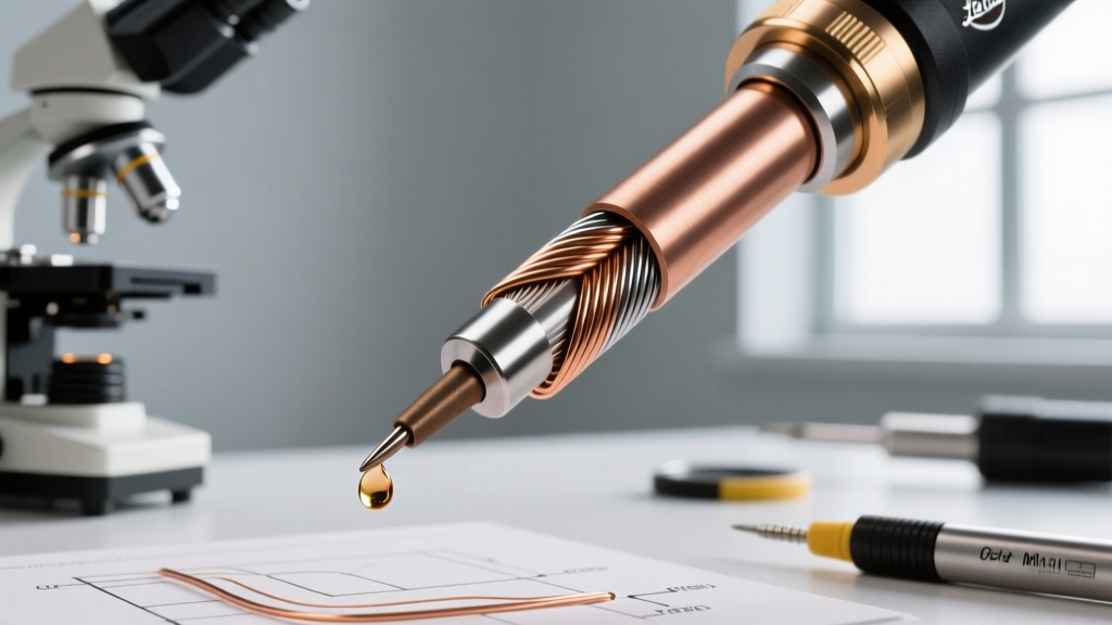
Before touching any digital menus, you must ensure the physical thermal coupling between the heating element and the soldering tip is flawless. Weller’s RT and XRT tip series feature an embedded thermocouple and heating element. If the tip is not seated correctly, the sensor reads the ambient air inside the barrel rather than the tip's working surface.
Proper Tip Seating Procedure
- Cool Down: Ensure the station is powered off and completely cool. Never change a Weller RT tip while hot without using the Weller WDH10T safety rest and tweezers.
- Inspect the Barrel: Look inside the heating element barrel. Use compressed air to blow out any oxidized scale or flux residue that might prevent the tip from seating flush.
- Insert and Twist: Slide the tip into the barrel and give it a gentle 10-degree twist. This aligns the internal sensor contacts.
- Secure the Collar: Thread the retaining collar on by hand. Do not use pliers. Tighten until snug, then back off a quarter-turn to allow for thermal expansion.
Expert Warning: If your Weller station constantly overshoots the target temperature and flashes an error code (like E03 or E04 on the WE1010NA), the tip is likely not fully seated, or the internal sensor wire is fractured. Forcing the collar can crush the ceramic heater, resulting in a $45 replacement part.
Phase 2: Calibration Procedures by Model
To calibrate accurately, you need a dedicated tip thermometer. While Weller offers proprietary sensors, the Hakko FG-100B Tip Thermometer (retailing around $165) remains the gold standard for cross-brand verification due to its fast-response K-type thermocouple.
Calibrating the Weller WE1010NA (Digital Standard)
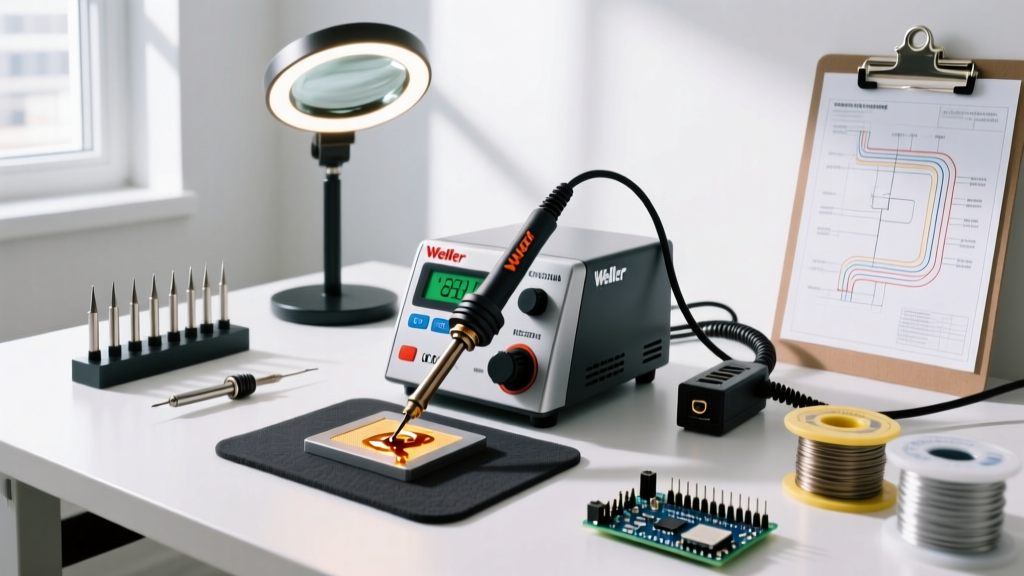
The WE1010NA (typically priced between $115 and $130) is the workhorse of modern DIY and professional benches. It features a hidden calibration menu designed to apply an offset to the internal PID controller.
- Preparation: Install a standard chisel tip (e.g., RT3 or XRT3). Power on the station and set the temperature to 350°C (662°F).
- Thermal Soak: Allow the station to reach the set temperature, then wait an additional 5 minutes. This ensures the entire thermal mass of the tip and heater is fully saturated.
- Measure: Apply a small bead of fresh leaded solder to the tip to act as a thermal bridge. Press the FG-100B sensor into the solder bead and record the stable reading.
- Enter Calibration Mode: Press and hold both the UP and DOWN arrow buttons simultaneously for 3 seconds. The display will flash 'CAL'.
- Apply Offset: Use the UP/DOWN arrows to adjust the displayed temperature until it exactly matches your external tip thermometer. For example, if the station reads 350°C but the thermometer reads 342°C, adjust the station display down to 342°C.
- Save: Press the MENU button once to lock in the offset and exit calibration mode.
Calibrating the Weller WD1001 (High-End Digital)
The WD1001 (approx. $489) offers a more sophisticated menu system with multi-language support and advanced profile management. Calibration is handled via the main settings matrix.
- Press the MENU button to access the main interface.
- Navigate to Settings > Device > Calibration.
- The system will prompt you for the current measured temperature. Enter the exact value read from your tip thermometer using the rotary dial.
- The WD1001’s microcontroller will automatically calculate the offset and apply it to the active heating profile. Press the dial to confirm.
Legacy WES51 (Analog Offset Adjustment)
Though largely superseded by digital models, thousands of WES51 analog stations remain in active service. Calibration on this unit requires opening the chassis. Warning: Only perform this if you are comfortable working near mains voltage.
- Unplug the station and remove the bottom enclosure screws.
- Locate the small trimpot (variable resistor) labeled 'CAL' on the main PCB.
- Power the station on (keeping hands clear of AC mains traces), set the dial to 700°F (371°C), and let it soak for 5 minutes.
- Measure the tip with your thermometer. Use a ceramic-tipped precision screwdriver to turn the CAL trimpot microscopically until the station's internal LED indicator (if equipped) or external meter matches the physical tip reading.
Tip Selection and Thermal Mass Matrix
Calibration is only half the battle; selecting the correct thermal mass for your specific PCB application is equally critical. Weller’s modern tip nomenclature dictates the power delivery and recovery speed.
| Tip Series | Compatible Handles | Thermal Mass | Best Application | Approx. Cost per Tip |
|---|---|---|---|---|
| RT Series | WSP80, WP80 | Low (40W) | 0402/0603 SMD, fine-pitch ICs | $10 - $12 |
| XRT Series | WXP80 | Medium-High (80W) | Mixed technology, heavy ground planes | $14 - $16 |
| XT Series | WSP150, WXP120 | High (120W+) | Large through-hole, heavy gauge wire | $15 - $18 |
Verifying Against IPC and NASA Standards
Once your offset is applied, you must verify the station's dynamic thermal recovery. Static calibration (measuring a tip in free air) does not reflect real-world soldering, where the copper pad acts as a massive heat sink.
To test dynamic recovery, apply the tip to a scrap PCB with a large ground plane. The temperature on your external meter will drop. According to the NASA Workmanship Training Program guidelines for high-reliability soldering, the station should recover to within 10°C of the set point within 2 to 3 seconds of initial contact. If your Weller station struggles to recover, the issue is not calibration—it is insufficient thermal mass. You must upgrade from an RT tip to an XRT or XT series tip to handle the joule heating requirements of the board.
Troubleshooting Common Calibration Failures
- Fluctuating Thermometer Readings: If your external tip thermometer jumps erratically, you likely lack a proper thermal bridge. Always use a tiny dab of fresh flux and solder between the tip and the K-type sensor wire.
- Station Refuses to Enter CAL Mode: On the WE1010NA, this usually indicates a locked menu. Perform a hard reset by holding the MENU button while powering the unit on to restore factory defaults, then attempt calibration again.
- Persistent Offset Drift: If you calibrate the station, but it drifts by more than 10°C over the next 48 hours, the internal thermocouple inside the soldering tip is degrading. Weller RT tips typically last 40-80 hours of active use with lead-free alloys. Replace the tip and recalibrate.
For ongoing firmware updates and advanced service manuals, always refer to the Weller Tools Official Support portal. Proper setup and rigorous calibration ensure your Weller soldering station remains a reliable, precision instrument for years of prototyping and production work.