
The Metallurgy of a Perfect Solder Joint
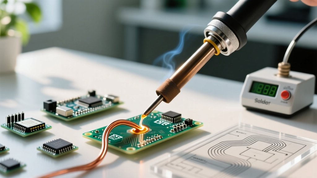
Mastering the soldering iron requires far more than simply melting metal onto a circuit board. At its core, soldering is a metallurgical process that creates an intermetallic compound (IMC) layer between the copper pad, the component lead, and the solder alloy. When you apply a properly calibrated soldering iron to a joint, the heat facilitates a chemical reaction where tin (Sn) and copper (Cu) form a Cu6Sn5 crystalline structure. This IMC layer is what provides the mechanical and electrical integrity of the connection. If your soldering iron temperature is too low, the IMC layer fails to form, resulting in a weak, high-resistance cold joint. If the temperature is too high or the dwell time exceeds 3 to 4 seconds, the IMC layer grows excessively thick and brittle, making the joint susceptible to mechanical fracturing under thermal cycling.
According to the IPC J-STD-001 standard, a compliant solder joint must exhibit proper wetting, a smooth concave fillet, and complete coverage of the lead. Achieving this consistently demands a deep understanding of thermal management, tip geometry, and flux chemistry.
Temperature Profiling by Alloy and Thermal Mass
One of the most pervasive myths in electronics DIY is that you should set your soldering iron to the maximum temperature to work faster. This is fundamentally incorrect and will rapidly oxidize your tip while damaging sensitive silicon. The correct approach is to set the iron 100°C to 130°C above the melting point of your specific solder alloy, adjusting slightly for the thermal mass of the pad.
| Solder Alloy | Melting Point | Ideal Iron Temp (Small Pads) | Ideal Iron Temp (Ground Planes) | Max Dwell Time |
|---|---|---|---|---|
| Sn63/Pb37 (Eutectic Leaded) | 183°C (361°F) | 300°C - 320°C | 340°C - 360°C | 2.0 - 3.0 seconds |
| Sn60/Pb40 (Standard Leaded) | 183°C - 190°C | 310°C - 330°C | 350°C - 370°C | 2.0 - 3.0 seconds |
| SAC305 (Lead-Free) | 217°C (423°F) | 350°C - 370°C | 380°C - 400°C | 2.5 - 4.0 seconds |
| Sn96.5/Ag3/Cu0.5 (High-Reliability) | 217°C - 220°C | 360°C - 380°C | 390°C - 410°C | 3.0 - 4.0 seconds |
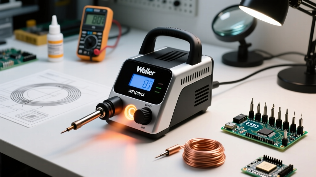
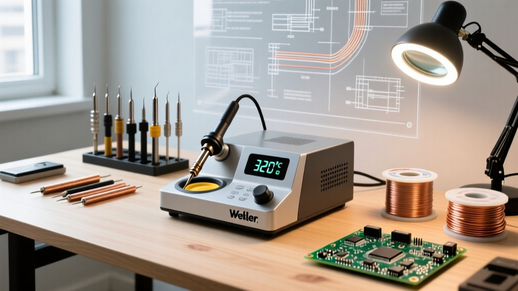
Equipment Context for 2026: When soldering heavy ground planes, standard 40W to 70W stations like the Weller WE1010NA ($120) or Hakko FX-888D ($115) will struggle with thermal recovery, causing the tip temperature to plummet upon contact. For high-thermal-mass boards, you need an active-tip sensing station. Systems like the JBC CD-2BE ($550+) or the Pace ADS200 ($380) detect the thermal load instantly and dump 100W+ directly into the cartridge, maintaining a stable 380°C even on 4-layer PCBs with heavy copper pours.
Selecting the Right Tip Geometry
The shape of your soldering iron tip dictates how efficiently thermal energy transfers from the heater core to the joint. Using the wrong geometry is a primary cause of pad lifting and cold joints.
- Chisel (D-Shape): The workhorse of through-hole and larger SMD (0805 and above) soldering. The flat edge maximizes surface area contact, ensuring rapid heat transfer. A 1/16-inch chisel (like the Hakko T18-D16) is ideal for standard DIP ICs and 0603 passives.
- Bevel (C-Shape): Features a concave cut at the tip. This is the mandatory choice for drag-soldering fine-pitch SOIC and QFP ICs. The concave surface holds a small reservoir of molten solder, allowing surface tension to pull the solder evenly across the pins without bridging.
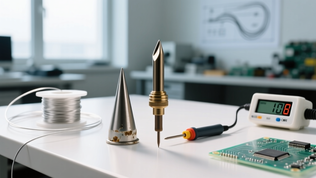
- Conical (B-Shape): Often mistakenly used by beginners for everything. Conical tips have a very small surface area at the point, resulting in poor thermal transfer. Reserve these strictly for micro-soldering 0201 components or delicate rework where precision outweighs thermal mass requirements.
- Knife (K-Shape): Excellent for cleaning up bridged pins on tight-pitch connectors and for dragging solder across large ground pads. The sharp edge can slice through micro-bridges instantly.
Flux Chemistry: The Unsung Hero
Flux is arguably more important than the solder itself. Its primary job is to strip away metal oxides from the copper pad and component lead, allowing the molten solder to wet the surfaces. According to IPC J-STD-004, fluxes are classified by their chemical composition and activity level. For modern electronics, you should exclusively use Rosin (RO) or Organic (OR) fluxes with Low (L) or Zero (0) halide content.
Step-by-Step: The 'Heat-Pad-Lead' Technique
For standard through-hole and SMD components, the industry-standard method endorsed by the NASA Workmanship Standards (NASA-STD-8739.3) follows a strict thermal sequence to ensure simultaneous heating of both surfaces.
- Prep and Tin: Clean the tip with dry brass wool. Apply a microscopic amount of fresh solder to the tip (tinning) to create a thermal bridge. This liquid metal bridge transfers heat 100x faster than air.
- Simultaneous Contact: Place the tinned flat of the chisel tip so it touches BOTH the copper pad and the component lead simultaneously. Do not just touch the lead.
- Count to Two: Hold the iron in place for 1.5 to 2 seconds. Allow the thermal mass of the pad and lead to reach the solder's melting point.
- Feed the Solder: Apply your solder wire to the opposite side of the joint, directly where the pad meets the lead—not to the iron tip itself. If the joint is hot enough, the solder will instantly flash and wick into the via or around the lead via capillary action.
- Withdraw in Sequence: Remove the solder wire first, then smoothly sweep the iron away at a 45-degree angle. This prevents a sharp spike (icicle) from forming on the cooling joint.
- Do Not Blow on It: Allow the joint to cool naturally. Blowing on a cooling joint disturbs the crystalline structure of the IMC layer, resulting in a grainy, fractured 'disturbed joint' that will eventually fail.
Troubleshooting Common Soldering Iron Failures
Even with premium equipment, poor technique manifests in distinct visual defects. Here is how to diagnose and correct them:
1. The Cold Joint
Visual Symptom: The solder looks dull, grainy, and forms a convex blob rather than a smooth, concave fillet.
Root Cause: Insufficient heat transfer to the pad. The solder melted on the iron tip but the pad never reached flow temperature.
Correction: Increase iron temperature by 20°C, switch to a wider chisel tip to increase surface area contact, and ensure you are heating the pad, not just the component lead.
2. Tombstoning (SMD Components)
Visual Symptom: A surface-mount capacitor or resistor stands up on one end, completely detaching from the opposite pad.
Root Cause: Uneven heating. One pad reached reflow temperature before the other, and the surface tension of the molten solder on the hotter side pulled the component upright.
Correction: Pre-heat the board to 100°C before hand-soldering, or use a wider bevel tip to heat both pads simultaneously. Ensure your PCB layout has symmetrical thermal relief on both pads.
3. Pad Lifting and Delamination
Visual Symptom: The copper pad peels away from the FR4 fiberglass substrate.
Root Cause: Excessive dwell time (holding the iron on the pad for >5 seconds) or using an iron set above 420°C.
Correction: Respect the 3-second dwell time limit. If the solder isn't flowing by 3 seconds, remove the iron, let the board cool for 10 seconds, add more liquid flux, and try again with a larger tip.
Tip Maintenance: Maximizing Cartridge Lifespan
Modern soldering iron tips are constructed from a copper core, plated with a layer of iron to prevent the solder from dissolving the copper, and finished with a thin layer of chromium on the non-wetting areas. The leading cause of tip death is 'dry burning'—leaving the iron on at 380°C without a protective layer of solder.
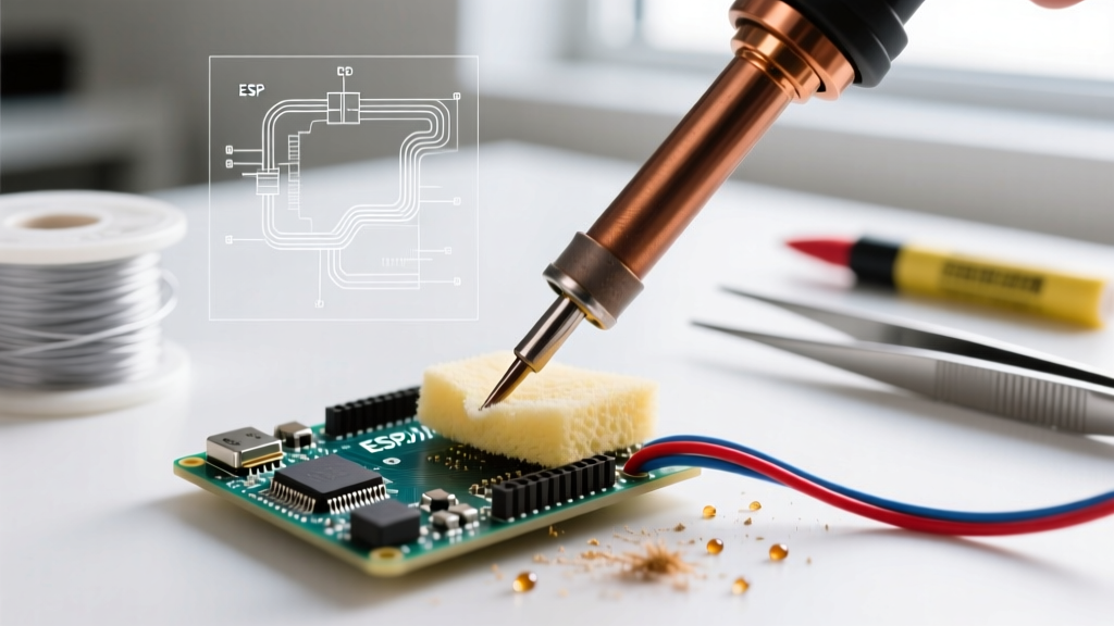
Always keep a small bead of solder on the tip when the iron is resting in its holder. Furthermore, abandon the traditional wet cellulose sponge. Plunging a 380°C tip into a room-temperature wet sponge causes severe thermal shock, leading to micro-fractures in the iron plating. Once the plating cracks, the molten solder eats through the copper core in a matter of hours. Instead, use dry brass wire wool. It cleans the oxidized flux residue without dropping the tip temperature or inducing thermal stress.
'A well-maintained Hakko T18 or Weller ETA tip should easily last through 50,000+ joints. If your tip is pitting or turning black and refusing to wet, the iron plating has been compromised. Do not sand it or use a file; you will expose the copper core and destroy the tip instantly.' — Electrical Flux Lab Notes, 2026
Safety and Fume Extraction
Soldering generates colophony fumes (from the rosin flux), which are known respiratory sensitizers and can trigger occupational asthma. The Cornell University Environmental Health and Safety guidelines mandate that soldering must never be performed in an unventilated space. Invest in a localized HEPA/Carbon fume extractor, such as the Hakko FA-400 or the Weller WFE2DX, and position the intake nozzle exactly 4 to 6 inches from the soldering joint to capture the plume before it reaches your breathing zone.
By respecting the metallurgy, utilizing the correct temperature profiles, and adhering to strict thermal sequencing, you will transform your soldering iron from a simple melting tool into a precision instrument capable of producing aerospace-grade connections.