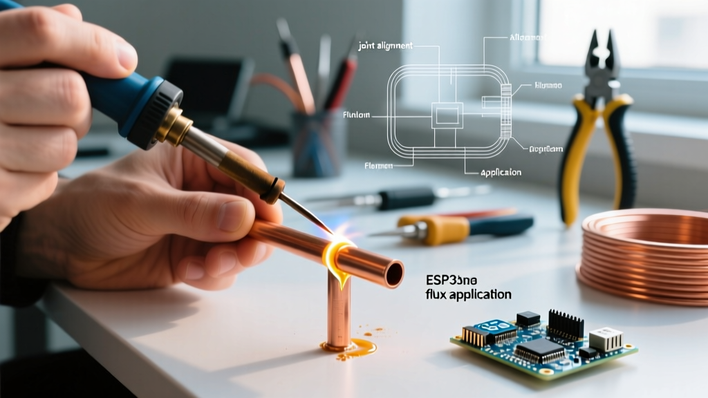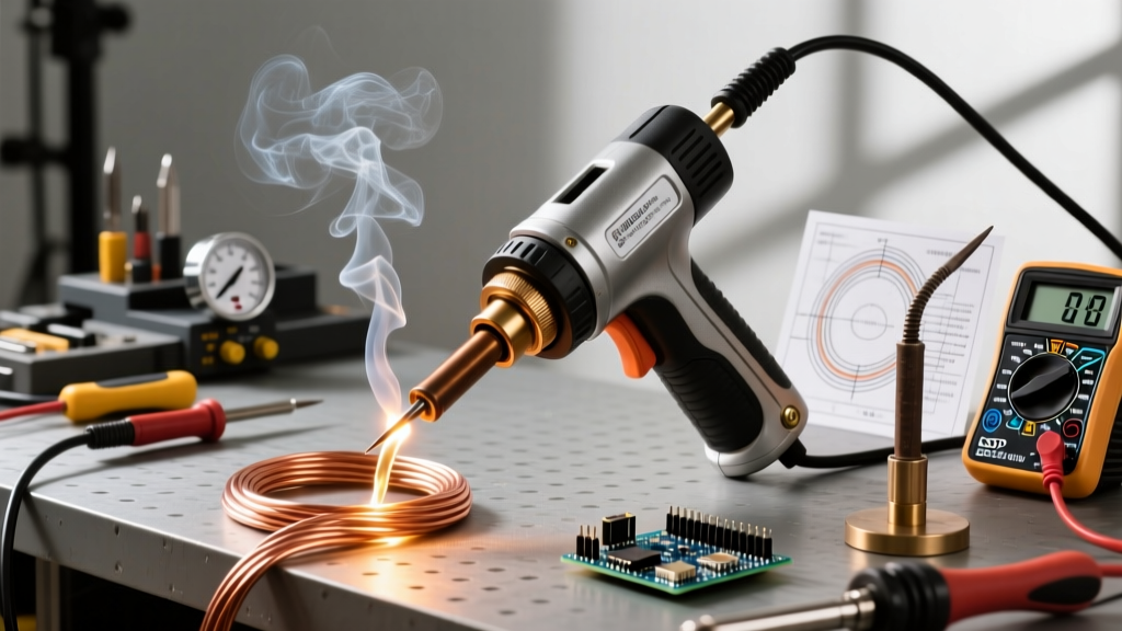

The 'Welder' Soldering Gun: Myth vs. High-Wattage Reality
In the electrical and heavy-DIY community, the term welder soldering gun is frequently tossed around to describe high-wattage, transformer-based soldering tools. Technically, welding involves melting the base metals to fuse them, while soldering relies on a lower-melting-point filler metal. However, when you are dealing with 4/0 AWG battery cables, heavy copper busbars, or thick structural grounding lugs, a standard 60W ceramic-core station simply will not suffice. You need brute-force thermal energy.
Heavy-duty transformer guns—like the legendary Weller D550 (260W/200W) or modern 300W generic equivalents—operate more like spot welders than traditional irons. They step down standard 120V AC line voltage to a massive secondary current (often exceeding 200 Amps) at a fraction of a volt. As of 2026, with the rise of high-current EV charging circuits and off-grid solar battery banks, mastering the setup and thermal calibration of these analog beasts is more critical than ever.
Anatomy of a Transformer-Based Heavy-Duty Gun
Before attempting calibration, you must understand the electrical pathway. Unlike a resistive heating element found in a pencil iron, a transformer soldering gun uses a heavy copper wire loop as both the heating element and the tip.
- Primary Winding: Connects to the AC mains via the trigger switch.
- Secondary Winding: A single, massive turn of copper that outputs roughly 0.15V to 0.25V AC.
- The Tip Loop: Completes the secondary circuit. The electrical resistance of the copper tip generates intense heat (up to 900°F+ in seconds) due to the massive amperage.
Expert Insight: Because the tip is literally a shorted secondary transformer winding, any mechanical looseness at the terminal block will cause micro-arcing. This destroys the brass terminals and creates massive voltage drops, leading to what users mistakenly diagnose as a 'burnt out transformer'.
Step 1: Mechanical Setup and Terminal Torque
The most common failure mode in a new or heavily used welder soldering gun is improper tip seating. The secondary circuit operates at upwards of 250 Amps. At this current level, even a milliohm of unwanted resistance from a loose terminal nut will generate localized heat and pitting.
Proper Tip Installation Procedure
- Clean the Threads: Use a brass wire brush and isopropyl alcohol to clean the brass terminal studs on the gun. Remove any old flux residue or oxidation.
- Insert the Tip: Bend your heavy-gauge copper tip wire to match the terminal spacing. Ensure the wire sits flat against the brass block.
- Apply Anti-Oxidant: Dab a microscopic amount of electrical contact grease (like Noalox) on the threads—not on the mating surfaces, which must remain metal-to-metal.
- Torque the Nuts: Using a nut driver, tighten the terminal nuts to 15-20 in-lbs. Do not overtighten, as brass studs can easily snap. If your gun features a separate locking screw for the tip wire, ensure it is driven firmly into the copper wire to bite through surface oxidation.
Step 2: Tip Selection and Secondary Amperage Matrix
Calibrating a transformer gun is not about turning a digital dial; it is about matching the thermal mass of the tip to the thermal mass of the workpiece. Using a tip that is too thin for a heavy lug will cause the tip to melt or oxidize instantly before the lug reaches the 450°F required to melt 60/40 or lead-free solder.
| Tip Wire Gauge | Target Application | Approx. Secondary Current | Heat-Up Time (to 600°F) |
|---|---|---|---|
| #12 AWG Copper | 4-8 AWG wire, heavy battery lugs, busbars | ~250 Amps | 3 - 5 seconds |
| #16 AWG Copper | 10-14 AWG wire, chassis grounds, thick PCB planes | ~180 Amps | 5 - 8 seconds |
| Flat Blade (Copper) | Sheet metal shielding, heavy coaxial braids | ~200 Amps | 8 - 12 seconds |
| #18 AWG (Standard) | 16-22 AWG wire, heavy connectors (NOT for lugs) | ~120 Amps | 10 - 15 seconds |
Step 3: Thermal Calibration via Pulse-Trigger Mapping
Transformer guns do not have thermostats. If you hold the trigger down continuously, the tip will eventually glow cherry red, oxidize, and melt. Therefore, you are the thermostat. Calibrating your technique is mandatory for repeatable, IPC-compliant joints.
In 2026, the best way to calibrate your trigger cadence is by using an entry-level thermal camera (such as the FLIR One Gen 3 or InfiRay P2) attached to your smartphone. Point the camera at a scrap piece of 6 AWG wire with a copper lug attached.
The 3-2-1 Pulse Method
- Initial Surge (3 Seconds): Squeeze the trigger fully. Watch the thermal camera. The tip will flash from ambient to 700°F+ almost instantly. Apply the tip to the workpiece, not the solder.
- Thermal Soak (Release for 2 Seconds): Release the trigger. The heat from the tip transfers into the massive copper lug. The lug temperature will rise while the tip temperature slightly drops.
- Maintenance Pulse (1 Second): Squeeze the trigger briefly to replenish the thermal energy lost to the workpiece.
- Feed Solder: Apply rosin-core solder to the opposite side of the joint. If the thermal mass is properly calibrated, the solder will wick into the wire strands via capillary action in under 2 seconds.
Verifying the Secondary Circuit (Multimeter Testing)
If your welder soldering gun is struggling to heat heavy lugs, do not assume the transformer is dead. Verify the secondary voltage under load.
- Setup: Set your digital multimeter to AC Millivolts (mV AC).
- Measurement: Place the probes directly across the two brass terminal nuts (with the tip installed).
- Expected Reading: With the trigger pulled, you should read between 150mV and 250mV AC (0.15V - 0.25V).
- Troubleshooting: If you read 0mV, the primary switch or winding is open. If you read line voltage (120V), the internal step-down transformer has suffered a catastrophic primary-to-secondary short. Stop using the tool immediately to avoid lethal shock.
Troubleshooting Common High-Wattage Failures
Even the best-maintained guns experience issues when subjected to the extreme thermal cycling of heavy electrical work. Here is how to diagnose the most frequent edge cases:
- Solder Balls Up and Refuses to Wet: The tip has oxidized due to continuous trigger pulling. Fix: File the tip wire lightly with a fine mill bastard file to expose bare copper, then immediately tin it with a high-rosin (RMA) flux solder while pulsing the trigger.
- Transformer Hums Excessively and Dips Lights: The secondary circuit is experiencing a dead short near the base of the tip, or the tip wire gauge is too thick for the transformer's VA rating. Fix: Ensure the tip loop is not touching itself, and verify you are using the correct AWG tip for the specific gun model (e.g., using a #12 tip on a 100W gun will overload the primary winding).
- Arcing and Green Flame at Terminals: Loose terminal nuts causing high-resistance micro-arcing. Fix: Disassemble, sand the brass terminals flat, and re-torque to 20 in-lbs.
Safety, Compliance, and Industry Standards
When using a high-wattage soldering gun for structural or electrical splices, you must adhere to established safety codes. According to the NFPA 70 (National Electrical Code), specifically Article 110.14, electrical splices must be mechanically secure and electrically conductive without relying solely on solder. Solder is used to seal and prevent corrosion, not to provide mechanical strength. A heavy-duty soldering gun is perfect for tinning and sealing a properly crimped lug, but it should never be used to 'glue' two wires together without a mechanical splice.
Furthermore, for aerospace or high-reliability automotive applications, referencing the NASA Workmanship Standards (NASA-STD-8739.3) provides excellent visual benchmarks for what a properly wetted, high-thermal-mass solder joint should look like. A properly calibrated gun will produce a bright, concave fillet with a visible feathered edge, whereas an under-calibrated thermal approach will result in a dull, convex 'cold' joint that is prone to catastrophic failure under vibration.
Mastering the welder soldering gun requires respecting the raw physics of transformer amperage. By focusing on mechanical terminal integrity, matching tip gauge to thermal mass, and utilizing a disciplined pulse-trigger technique, you can achieve flawless, high-current joints that will outlast the equipment they power.