
The Metallurgy of Soldering: Why Timely Weller Soldering Iron Tips Replacement Matters
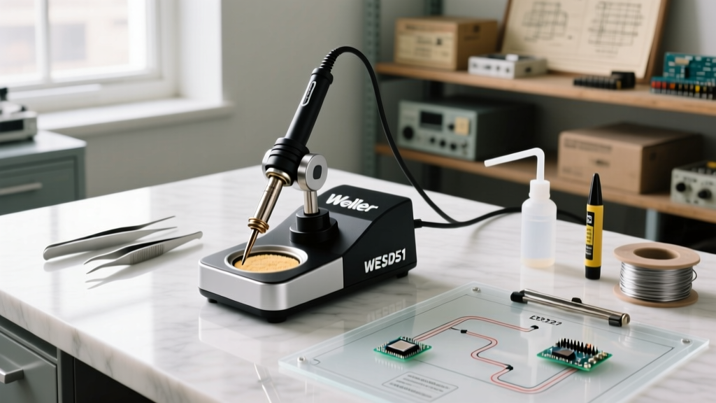
Soldering with a degraded Weller tip isn't just frustrating; it actively compromises joint integrity, increases dwell time, and risks lifting sensitive SMD pads. Whether you are running a legacy analog WES51, a digital WE1010NA, or a high-end WX1012 station, knowing exactly when and how to execute a Weller soldering iron tips replacement is a fundamental skill for any serious electronics technician or DIY engineer. In 2026, with lead-free SAC305 (Tin-Silver-Copper) alloys dominating both manufacturing and repair benches, tip degradation happens significantly faster than it did with traditional 63/37 SnPb solders. Lead-free fluxes are inherently more aggressive, and the higher melting points (217°C to 227°C) require sustained tip temperatures between 350°C and 380°C, accelerating oxidation and iron plating dissolution.
This expert guide bypasses generic advice and dives deep into the metallurgy, compatibility matrices, and bench-tested procedures required to maximize your Weller investment, ensuring optimal thermal transfer and compliance with industry workmanship standards.
Decoding the Weller Tip Ecosystem: XDS, RT, ET, and XT Families
Before initiating a replacement, you must verify cross-compatibility. Weller has segmented its tip architecture to match specific heating elements and sensor configurations. Using the wrong series will result in catastrophic sensor failure or total thermal loss.
| Tip Series | Compatible Irons / Stations | Wattage & Sensor Type | Primary Use Case & Pricing (2026) |
|---|---|---|---|
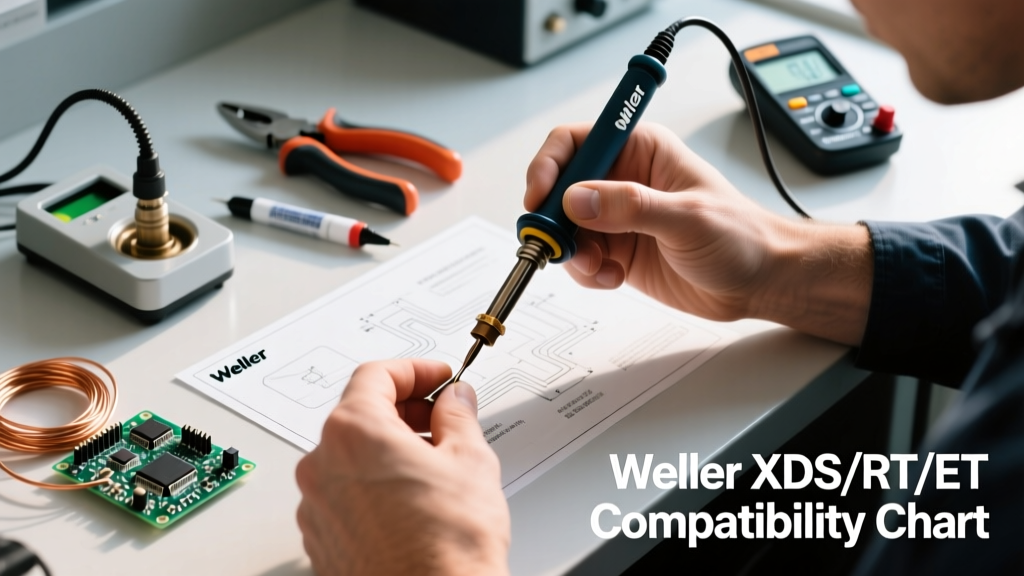
| XDS | WE1010, WE1010NA, WEL1012 | 70W / Integrated Thermocouple | General purpose, lead-free through-hole, SMD. ($11 - $14 per tip) |
| RT | WXMP, WX1012, WT1012 | 40W / Integrated Sensor in Tip | Micro SMD, 0201/0402 components, precision rework. ($15 - $19 per tip) |
| ET | WES51, WESD51, PES51 | 50W / Element-Mounted Sensor | Legacy through-hole, heavy gauge wire, hobbyist use. ($7 - $9 per tip) |
| XT | WSP80, WP80, WSD81 | 80W / Heavy-Duty Thermocouple | Massive ground planes, multilayer RF boards, thick copper. ($12 - $16 per tip) |
Expert Note: The RT series is unique because the heating element and temperature sensor are built directly into the tip cartridge. When you replace an RT tip, you are effectively replacing the entire thermal engine of the handpiece. This accounts for the higher price point but guarantees zero thermal lag.
The 4 Telltale Signs of Tip Failure (Beyond Simple Discoloration)
Novices often mistake temporary flux carbonization for permanent tip death. As an expert, you must differentiate between surface contamination and structural metallurgical failure. According to the NASA-STD-8739.3 Workmanship Manual, a soldering iron tip must maintain uniform wetting across its working surface to ensure reliable intermetallic compound (IMC) formation.
1. Non-Wetting and the Black Oxide Layer
When the iron plating reacts with atmospheric oxygen at high temperatures, it forms a black, glassy oxide layer. Solder will ball up and roll off. While mild oxidation can sometimes be rescued with a tip tinner (a mixture of abrasive powder and SAC solder), deep oxidation means the iron layer is compromised. If tip tinner fails to restore a shiny silver wetting surface within 3 seconds, immediate Weller soldering iron tips replacement is mandatory.
2. Pitting and Cratering (Iron Plating Dissolution)
Aggressive halide-based fluxes, combined with temperatures exceeding 400°C, will literally eat through the microscopic iron plating that protects the copper core. Once you see physical craters or a rough, sandpaper-like texture on the tip surface, the copper is exposed. The tip will rapidly dissolve into the solder bath and must be discarded immediately to prevent copper contamination in your joints.
3. Thermal Lag and Carbon Seizing
If your Weller WE1010 reads 360°C on the display, but the solder takes 5+ seconds to melt on a standard pad, you likely have a thermal transfer failure. This is often caused by a microscopic layer of carbonized flux trapped between the Weller heating element and the inner barrel of the tip. This acts as a thermal insulator. While cleaning the element can help, severely warped tips require replacement.
4. Micro-Fractures from Thermal Shock
Using a soaking wet cellulose sponge drops the tip temperature by up to 150°C in milliseconds. Over hundreds of cycles, this thermal shock causes micro-fractures in the iron plating. Under a magnification lamp, these look like tiny spiderweb cracks. Solder will seep into these cracks, destroying the tip from the inside out.
Precision Procedure: Step-by-Step Tip Replacement
Improper removal techniques can snap the fragile sensor pin on RT tips or strip the threads on XDS retaining nuts. Follow this bench-tested protocol for safe extraction and installation.
- Controlled Cool-Down: Turn off the station and allow the iron to cool to approximately 50°C - 60°C. Never remove a tip while it is at operating temperature (risk of severe burns and element damage), but avoid letting it cool completely to room temperature if it has heavy flux buildup, as carbonized flux acts like glue and will seize the tip to the element.
- Retaining Nut Extraction: For XDS and ET series, use the provided Weller barrel wrench or a small socket to loosen the retaining nut. For RT micro tips, you must use the specialized Weller B500 or B501 wrench to avoid crushing the delicate tip shaft.
- Element Inspection: Once the old tip is slid off, inspect the heating element (or sensor pin for RT). If you see black carbon scoring, gently wipe it with a lint-free swab dampened with 99% isopropyl alcohol. Do not use sandpaper or files, as this will alter the physical tolerances and ruin the thermal coupling.
- Seating the New Tip: Slide the new genuine Weller tip onto the element. Ensure it bottoms out completely. For RT tips, align the flat notch on the tip base with the sensor housing to prevent pin bending.
- Torque and Tinning: Hand-tighten the retaining nut, then give it a quarter-turn with the wrench. Power on the station to 300°C. Immediately apply a generous amount of rosin-core solder (like Kester 245 or 186) to coat the entire working surface before the tip reaches full operating temperature, preventing instant flash-oxidation.
Expert Bench Hacks to Triple Tip Lifespan
Replacing tips is expensive, especially for micro-soldering setups. Implement these operational habits to extend the life of your Weller tips from a few weeks to several months.
- Ditch the Wet Sponge for Brass Wool: As mandated by modern IPC J-STD-001 Requirements for high-reliability soldering, minimizing thermal shock is critical. Dry brass wire wool (often sold as tip cleaners) removes oxidized solder and flux residue without dropping the tip temperature, preserving the iron plating's structural integrity.
- Utilize Auto-Off / Sleep Modes: Leaving a Weller WE1010 idling at 380°C for 10 minutes destroys the tip faster than 2 hours of active soldering. Configure your station's sleep mode to drop the temperature to 150°C after 5 minutes of inactivity, or turn it off entirely.
- Use the Largest Tip Possible: A common mistake is using a micro RT MS (0.8mm) tip to solder large ground pads. The station will max out the 40W heater, keeping the tip at extreme temperatures continuously. Switching to an RT GW (knife) or a larger chisel tip increases thermal mass, allowing you to lower the station temperature to 340°C while achieving faster wetting times.
- Pre-Tin Before Powering Down: Always leave a massive blob of cheap, leaded 63/37 solder on the tip before turning off the station. This "sacrificial layer" oxidizes in place of the iron plating as the tip cools. Wipe it off and re-tin with your working alloy upon the next power-up.
Edge Cases: Troubleshooting Thermal Lag and Sensor Misalignment
The "Loose Fit" Thermal Transfer Issue
If your new XDS tip feels slightly loose inside the retaining nut even when fully tightened, you are experiencing a manufacturing tolerance stack-up. This air gap will cause severe thermal lag. Fix: Apply a microscopic smear of high-temperature thermal paste (designed for CPU/GPU applications) to the outside of the heating element before sliding the tip on. This bridges the microscopic air gaps and restores instantaneous thermal transfer.
RT Series Sensor Pin Bending
The RT series features a delicate sensor pin that mates with the handpiece. If you force the tip in at a slight angle, the pin will bend, resulting in an "Error 3" or "Sensor Open" code on your WT1012 display. Fix: Never use pliers to bend the pin back. Use a precision jeweler's screwdriver to gently coax it back to a 90-degree angle under a stereo microscope. If the pin base is cracked, the tip is e-waste.
Sourcing Authentic Weller Tips in 2026
The market is currently flooded with counterfeit Weller tips sold in bulk on third-party marketplaces for $2 to $3 each. These counterfeits use inferior copper alloys, lack proper iron plating, and feature misaligned thermocouples that can cause your Weller station to overheat and melt the handpiece housing. According to the Weller Tools Official Knowledge Base, only authorized distributors can guarantee the metallurgical specifications required for safe operation.
Always source your replacement tips from authorized, tier-1 electronic component distributors such as Digi-Key, Mouser, Farnell, or Newark. Expect to pay between $11 and $14 for standard XDS tips, and up to $19 for specialized RT micro-cartridges. While the upfront cost is higher, the consistent thermal performance and adherence to IPC workmanship standards make genuine Weller tips the only viable choice for professional and serious DIY electronics work.
By understanding the metallurgy of failure, adhering to strict replacement protocols, and optimizing your bench habits, you can master Weller soldering iron tips replacement and ensure every joint you make is structurally sound and electrically flawless.