
The Physics of Transformer Guns vs. Heavy Wire
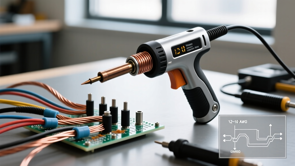
Unlike modern ceramic-heater soldering stations that rely on PID controllers and digital thermocouples, transformer-based soldering guns operate on a fundamentally different physical principle. Tools like the Weller D550 (200W/260W) or the heavier D650 (260W/325W) step down standard 120V AC line voltage to a fraction of a volt while pushing massive amperage—often exceeding 250 amps—directly through the tip. When configuring a soldering gun and wire assembly for high-current applications (such as 8 AWG to 2 AWG battery cables, RC LiPo wiring, or automotive harnesses), standard temperature dials do not exist. Instead, calibration involves mechanical tip seating, electrical load testing, and precise thermal profiling.
Copper is an exceptional thermal conductor. A 4 AWG stranded copper wire acts as a massive heat sink, rapidly pulling thermal energy away from the joint. If your setup is not calibrated to overcome this thermal mass, the result is a cold, brittle joint that will fail under high-amperage loads. This tutorial provides a professional-grade setup and calibration protocol for heavy-duty transformer guns.
Step 1: Mechanical Setup and Tip Seating
The most common failure mode in transformer guns is localized arcing at the tip connection. The tip itself acts as the secondary winding of the transformer. It is held in place by two brass or copper nuts on the transformer's output terminals. If these nuts are even slightly loose, the increased electrical resistance generates intense, localized heat at the terminal block rather than at the working end of the tip. This causes voltage drop, arcing, and eventual terminal melting.
Calibration Procedure for Tip Seating
- Disassemble and Clean: Remove the tip nuts and the tip. Use a brass wire brush to clean the terminal faces and the inner loops of the tip. Wipe all contact surfaces with 99% isopropyl alcohol to remove oxidation and oils.
- Apply Conductive Paste: Apply a micro-thin layer of electrical contact grease (such as NO-OX-ID A-Special) to the mating surfaces. This prevents future galvanic corrosion and ensures maximum current transfer.
- Precision Torque: Reinstall the tip and nuts. Do not use pliers, which can deform the soft brass nuts. Use a properly sized nut driver or socket to tighten the nuts to approximately 15-20 inch-pounds. The connection must be mechanically rigid; any micro-movement under 200A of current will cause arcing.
Step 2: Electrical Load Calibration and Verification
Before applying the gun to expensive heavy-gauge wire, you must verify the transformer's output. Over time, transformer windings can degrade, or internal switches can develop carbon buildup, reducing the effective wattage delivered to the tip.
Required Test Equipment
- True-RMS Digital Multimeter (e.g., Fluke 87V or Brymen BM869s)
- AC Clamp Meter capable of reading low-voltage/high-current (or a calibrated shunt resistor)
- K-Type Thermocouple with a surface probe
Testing Open-Circuit Voltage (OCV)
Set your True-RMS multimeter to AC Volts. Place the probes directly on the extreme working ends of the soldering gun tip. Pull the trigger to the high position (usually the second click). A properly calibrated Weller D550 should read between 0.18V AC and 0.24V AC. If the reading is below 0.15V AC, your internal switch contacts may be pitted, or the primary winding is failing, and the gun will lack the thermal punch required for heavy wire.
Step 3: Thermal Profiling the Soldering Gun and Wire Joint
The relationship between your soldering gun and wire gauge dictates the exact dwell time required to achieve a proper metallurgical bond without melting the wire's insulation. Heavy-gauge silicone or PVC insulation will melt and pull back if the heat cycle is too long. We use thermal profiling to map the exact timing.
According to the NASA Electronic Parts and Packaging (NEPP) program guidelines for soldering (NASA-STD-8739.3), thermal damage to wire insulation and underlying strands is a critical defect. Heat must be applied rapidly and removed immediately upon solder flow to prevent insulation degradation and copper annealing.
Profiling Protocol
- Strip exactly 3/8" of insulation from your target wire (e.g., 8 AWG).
- Attach the K-Type thermocouple bead directly to the exposed copper strands using a small piece of Kapton tape.
- Apply a generous amount of mildly activated rosin flux (e.g., Kester 186) to the wire.
- Bring the pre-heated gun tip to the wire. Start a stopwatch.
- Record the time it takes for the thermocouple to read 183°C (the melting point of standard 63/37 eutectic solder).
- Remove the gun and allow the wire to cool. Repeat three times to establish an average dwell time.
Thermal Mass Reference Matrix
| Wire Gauge (AWG) | Recommended Gun Wattage | Tip Style | Target Temp (°C) | Max Dwell Time (63/37) | Max Dwell Time (SAC305) |
|---|---|---|---|---|---|
| 10 AWG | 150W - 200W | Standard Chisel | 220°C | 3 - 4 seconds | 5 - 6 seconds |
| 6 AWG | 260W - 325W | Heavy Chisel / Loop | 240°C | 5 - 7 seconds | 8 - 10 seconds |
| 2 AWG | 325W+ (or dual-gun) | Custom Formed Loop | 260°C | 9 - 12 seconds | Not Recommended |
Flux, Solder Alloys, and Heavy-Gauge Wire
When pairing a soldering gun and wire for high-current joints, the choice of solder alloy is just as critical as the tool itself. For non-RoHS DIY, automotive, and RC applications, 63/37 Tin/Lead eutectic solder (such as Kester 24-6337-00278 in 0.062" diameter) remains the gold standard. It melts at a sharp 183°C, requiring significantly less thermal energy to flow into the interstitial spaces of heavy stranded wire.
If you are mandated to use lead-free solder (such as SAC305, which melts at ~217°C), your soldering gun must be operated on its highest trigger setting, and the dwell times will increase by approximately 40%. However, prolonged heating of heavy-gauge wire to achieve SAC305 flow risks annealing the copper strands, reducing their mechanical tensile strength and electrical conductivity. Always use a high-solids rosin flux to accelerate heat transfer and reduce surface tension.
Troubleshooting Common Failure Modes
Even with a calibrated setup, operator error can lead to catastrophic joint failures. Referencing the IPC J-STD-001 requirements for soldered electrical assemblies, here are the most common edge cases and their solutions:
- The "Cold" or "Disturbed" Joint: Characterized by a dull, grainy, or cracked appearance. Cause: The wire moved before the solder fully solidified, or the gun lacked the wattage to bring the entire wire mass above the melting point. Fix: Upgrade to a higher wattage gun (e.g., moving from a D550 to a D650) and use a custom loop tip that wraps entirely around the wire barrel to maximize surface contact area.
- Melted or Receded Insulation: Cause: Dwelling on the high trigger for more than 10 seconds, allowing capillary action to wick molten solder under the insulation jacket, which then solidifies and creates a rigid stress point. Fix: Pre-tin the wire strands separately before inserting them into a connector barrel. This reduces the final joint dwell time to under 2 seconds.
- Terminal Block Scorching: Cause: As mentioned in Step 1, loose tip nuts causing arcing. Fix: Immediately cease operation, disassemble, and re-torque the terminal nuts. Referencing Weller Tools technical support documentation, operating a gun with compromised terminals will permanently destroy the transformer's secondary output leads.
Final Calibration Checklist
Before committing to a production run of battery cables or high-amperage harnesses, run through this final verification checklist:
- Tip nuts torqued and free of carbon buildup.
- Open-circuit AC voltage verified at the tip extremities.
- Thermal profile mapped with a K-Type thermocouple for the specific AWG wire being used.
- Proper flux chemistry selected (Rosin-based for copper).
- Workspace ventilated to handle high-volume rosin smoke generated by heavy wire joints.
By treating your transformer gun as a high-current electrical system rather than a simple heating element, you ensure metallurgical integrity, maximize the lifespan of your tool, and guarantee safe, high-amperage wire connections.