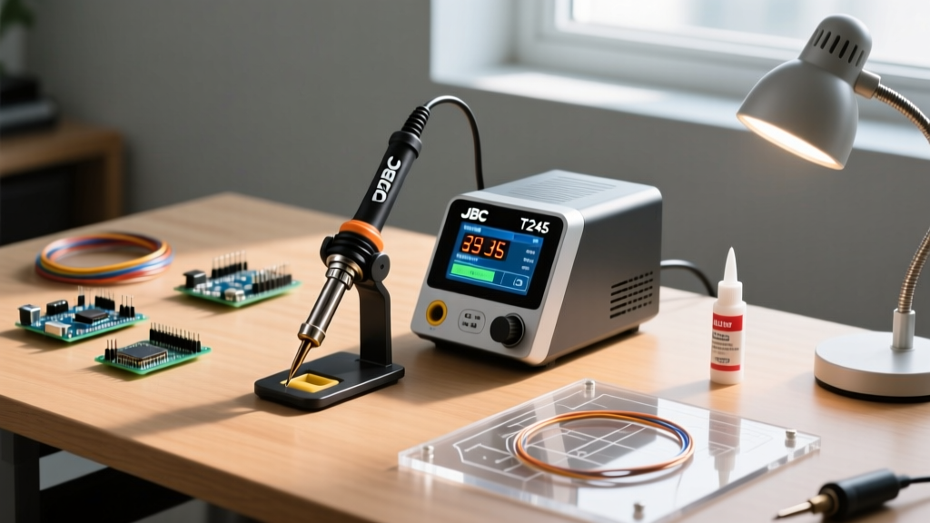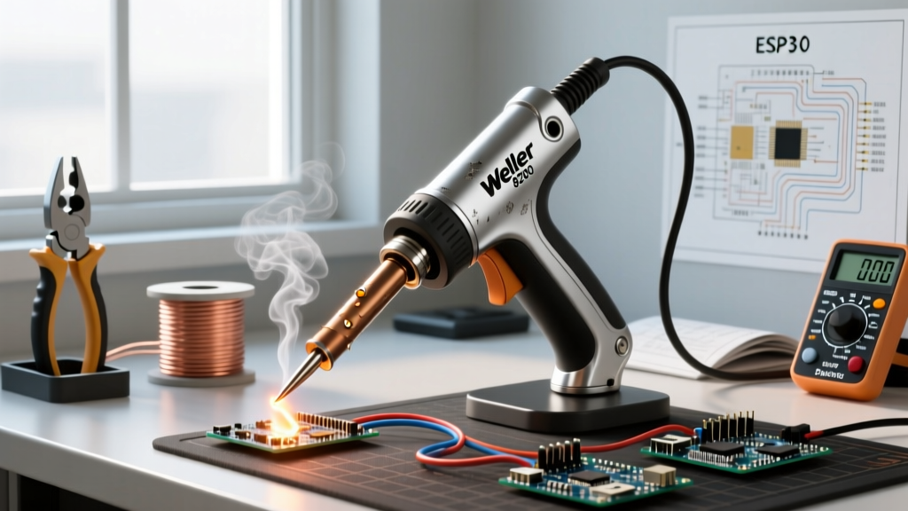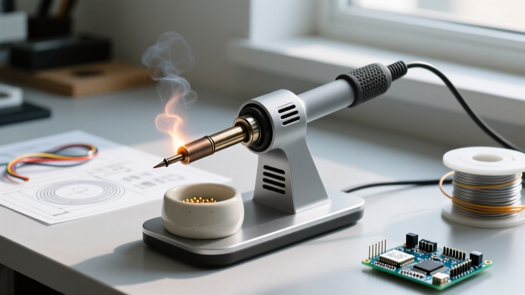

Most electronics hobbyists and even some seasoned professionals treat the soldering iron stand as a mere accessory—an afterthought included in the box with their heating element. However, in modern 2026 workstations featuring high-wattage USB-C irons like the Pinecil V2 or sophisticated active-tip stations like the JBC CD-2BQE, the stand is a critical thermal, metallurgical, and safety interface. How you leave your soldering iron in stand mechanisms directly dictates tip longevity, bench safety, and workflow ergonomics.
In this feature deep dive, we examine the physics, materials, and failure modes of soldering iron stands, providing actionable data to optimize your soldering environment.
The Thermodynamics of a Soldering Iron in Stand
When a soldering iron is active but not in use, it must dissipate heat safely without cooling down so much that recovery times become impractical. The stand acts as a localized thermal management system. When you rest a 350°C tip in a standard brass coil stand, the physical contact area between the tip and the metal coil is roughly 15mm² to 20mm².
This contact creates a conduction pathway. If the stand is heavily weighted and acts as a massive heat sink, it will aggressively pull thermal energy away from the tip. Modern PID-controlled stations will detect this temperature drop and pulse the heating element to compensate, leading to localized overheating of the tip's ceramic heater core. Conversely, high-temperature polymer cradles act as insulators, maintaining the tip's ambient temperature but risking heat buildup in the immediate airspace.
Tip Metallurgy and Oxidation Rates
To understand why resting position matters, you must understand tip construction. A standard soldering tip consists of a high-conductivity copper core, electroplated with a 100 to 150-micron layer of iron to prevent solder dissolution, followed by a micro-thin chromium barrier layer, and finally a tinned working surface.
When a soldering iron in stand setups leaves the tip exposed to ambient oxygen at 350°C, oxidation accelerates exponentially. According to Hakko's official tip care guidelines, leaving a tip idle at high temperatures without a protective layer of fresh solder causes the iron plating to oxidize, creating a black, non-wettable crust that ruins thermal transfer.
Material Breakdown: Coil vs. Cradle vs. Holster
The market offers three primary stand architectures, each with distinct thermal and physical properties. Below is a comparative analysis of standard 2026 workstation stand materials.
| Stand Type | Primary Material | Weight (Approx) | Heat Dissipation | Best Use Case |
|---|---|---|---|---|
| Traditional Coil | Brass / Stamped Steel | 250g - 350g | High (Conduction) | General purpose, budget stations |
| Silicone Cradle | High-Temp Silicone / Aluminum | 150g - 200g | Low (Insulation) | ESD-safe environments, lightweight setups |
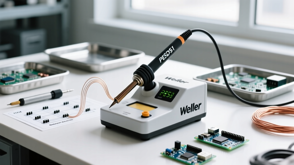
| Integrated Holster | Die-Cast Zinc / Bakelite | 450g+ (Station bound) | Managed (Active sleep) | Precision SMD work, JBC/Weller high-end |
For heavy-duty through-hole work, the traditional brass coil (like the Hakko 602) remains a favorite due to its durability and ability to scrape excess solder off the tip. However, for fine-pitch SMD work, integrated holsters that trigger a 'sleep' mode via magnetic reed switches or Hall effect sensors are vastly superior, as they drop the tip temperature to 150°C when the soldering iron in stand is detected, halting oxidation entirely.
The Thermal Shock Phenomenon: Sponges vs. Brass Wool
The cleaning mechanism housed within the stand is just as critical as the structural support. For decades, the wet cellulose sponge was the industry standard. Today, it is recognized as a primary cause of premature tip failure due to thermal shock.
The Physics of Micro-Fracturing
A standard cellulose sponge holds water at room temperature (approx. 20°C). When you wipe a 350°C tip across the wet sponge, the surface temperature of the tip drops instantaneously. This creates a Delta T (temperature differential) of over 300°C in a fraction of a second.
This extreme thermal shock causes the 100-micron iron plating to contract rapidly while the copper core beneath it remains expanded. Over hundreds of cycles, this induces micro-fissures in the iron plating. Once these microscopic cracks form, aggressive flux residues penetrate the barrier and attack the copper core, leading to catastrophic tip pitting and dissolution. The IPC J-STD-001 standards for soldered electrical assemblies emphasize maintaining strict thermal profiles to prevent damage to both components and tooling, a principle that extends to tip maintenance.
The Brass Wool Solution
To eliminate thermal shock, modern workstations utilize brass wool (curly brass shavings) housed in the stand's base. Brass has a melting point of roughly 900°C and excellent thermal mass. When a tip is plunged into brass wool, the shavings mechanically scrape away oxidized solder and flux residue without dropping the tip's temperature below the melting point of SAC305 lead-free solder (217°C). This preserves the iron plating and ensures the tip is instantly ready for the next joint.
Ergonomics and the Angle of Repose
The angle at which the soldering iron in stand rests profoundly impacts user fatigue and bench safety. Most generic stands position the iron at a 45-degree angle. While adequate for casual use, this angle forces the user to execute a wide, sweeping arc to pick up the iron, increasing the risk of brushing against the hot barrel or the cord.
Optimizing for Pick-and-Place Workflows
Ergonomic studies in manufacturing environments suggest that a 60-degree to 70-degree resting angle is optimal for high-volume SMD soldering. This steeper angle aligns the handle more closely with the natural resting position of the human wrist, reducing the rotational force required to grasp the tool. Stands like the Weller WDH10T offer adjustable cradles that allow technicians to dial in this precise angle, minimizing repetitive strain injuries (RSI) during long debugging sessions.
Failure Modes: Slips, Cord Drag, and Bench Fires
A soldering iron operating at 400°C is a severe fire hazard. The most common failure mode of a standalone unit is tipping. This is rarely caused by the iron itself, but rather by cord drag.
- PVC Cord Memory: Older or cheaper irons use thick PVC cords that develop a 'memory' curl. When placed in a lightweight stamped-steel stand (often weighing under 200g), the lateral tension of the curled cord shifts the center of gravity outside the stand's base footprint, causing it to tip over onto the workbench.
- Vibration Transfer: In shared maker spaces or manufacturing floors, heavy machinery or even aggressive typing can vibrate a desk. A smooth, cylindrical iron handle resting in a smooth brass coil can slowly rattle its way out of the stand if the angle is too shallow.
- Solution: Always pair heavy die-cast bases (400g+) with irons that feature high-flexibility, low-memory silicone cords. If using a lightweight portable stand, ensure it features a mechanical retention clip or a magnetic tether.
Expert Maintenance Protocol Before Resting
Never leave a soldering iron in stand with a bare, oxidized tip. Implementing a strict tinning protocol before releasing the handle will double or triple the lifespan of your tips. Follow this exact sequence:
- Flash Clean: Plunge the tip into brass wool 3 to 4 times to remove carbonized flux and old, oxidized solder.
- Apply Fresh Alloy: Immediately apply a generous amount of fresh, flux-cored solder (preferably a high-reliability alloy like SAC305 or Sn63/Pb37) to the entire working surface of the tip.
- The 'Solder Blob' Method: Leave a visible, oversized blob of solder on the very apex of the tip. This sacrificial layer will oxidize in the ambient air, protecting the underlying iron plating and the tinned layer beneath it.
- Rest and Power Down: Place the iron securely in the stand. If using a station with sleep mode, engage it. If not, power off the station immediately after the sacrificial blob is applied.
Pro Tip: Never use sandpaper, files, or abrasive pads to clean a modern soldering tip. These tools will instantly strip the 100-micron iron plating, exposing the copper core and destroying the tip in a matter of seconds.
Conclusion
The way you manage your soldering iron in stand setups is a hallmark of professional discipline. By understanding the thermodynamics of heat dissipation, eliminating thermal shock by switching to brass wool, and managing cord drag to prevent catastrophic tipping, you protect both your investment in precision tooling and your physical workspace. Upgrade your stand architecture to match the sophistication of your heating element, and your tips will reward you with thousands of flawless, oxidation-free joints.