
Introduction to Precision Soldering Station Setup
Unboxing a new Weller soldering iron kit is the first step toward professional-grade electronics assembly, but plugging it in and turning the dial is not enough. Out of the box, environmental factors, thermocouple variances, and tip seating tolerances can cause the displayed temperature to deviate from the actual tip temperature. According to the IPC J-STD-001 standard for high-reliability soldering, temperature control at the tip must be maintained within strict tolerances (typically ±5°C or ±9°F) to prevent cold solder joints or thermal damage to sensitive surface-mount components.
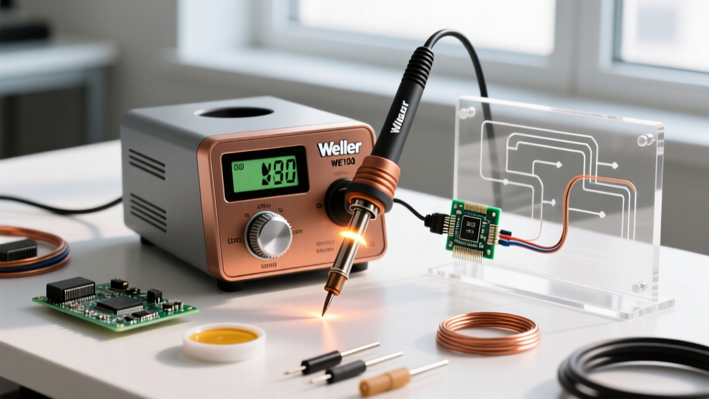
In this comprehensive 2026 tutorial, we will walk through the exact hardware setup, digital calibration, and analog offset adjustment procedures for the most popular Weller stations on the market: the digital WT1012 and the analog WE1010NA. Whether you are building a new DIY lab or upgrading a professional rework bench, these steps ensure your iron performs to exact engineering specifications.
Phase 1: Hardware Assembly and Tip Seating
Before attempting any thermal calibration, the physical hardware must be assembled correctly. A poorly seated tip will introduce massive thermal lag, rendering any calibration data useless.
- Station Placement: Position the Weller base station on a static-dissipative mat. Ensure the rear ventilation louvers have at least 4 inches of clearance to prevent internal sensor drift caused by heat buildup.
- Cord Connection: Align the pins on the silicone soldering iron handpiece connector with the socket on the station. Screw the locking ring down firmly. A loose connection introduces resistance, which the station's microcontroller may misinterpret as temperature data.
- Heating Element Inspection: Before sliding the tip on, inspect the ceramic heating element. For the Weller WP80 (used in WT1012 kits) or WEP80 (used in WE1010NA kits), the sensor pin should be perfectly centered and free of oxidation.
- Tip Seating: Slide the ETA or RT series tip over the ceramic heater. Push it all the way back until it bottoms out against the sensor flange. Thread the locking nut on by hand until snug. Do not use pliers to tighten the locking nut, as this can crack the internal ceramic core.
Phase 2: Weller Station Calibration Matrix
Different Weller kits utilize different internal logic for temperature verification. Use the table below to identify the calibration methodology required for your specific 2026 kit model.
| Weller Model | Display Type | Calibration Tool Required | Adjustment Range | Avg. 2026 Price |
|---|---|---|---|---|
| WT1012 | Digital LCD | Front Panel Buttons | ±90°F (±50°C) | $159.00 |
| WE1010NA | Digital LCD | Flathead / CAL-1 Tool | ±90°F (±50°C) | $119.00 |
| WES51 (Legacy) | Analog Dial | Small Flathead Screwdriver | ±90°F (±50°C) | $99.00 |
| WXA2 | Digital OLED | Menu UI / Weller Software | ±180°F (±100°C) | $450.00 |
Phase 3: Digital Calibration Procedure (WT1012 / WE1010NA)
For digital stations, the internal microcontroller allows you to input a manual temperature offset. This requires a high-accuracy K-type thermocouple and a reliable digital multimeter (DMM) like the Fluke 87V.
Step 1: Thermocouple Placement
The most common mistake in soldering calibration is simply resting the thermocouple bead on top of the tip. For accurate readings, you must use a tip thermocouple simulator or wrap the bare K-type wire tightly around the working end of the ETA tip, securing it with a small piece of high-temp Kapton tape or applying a dab of thermal paste to ensure maximum thermal transfer.
Step 2: Entering Calibration Mode
- For the WT1012: Press and hold the 'Menu' and 'Down' arrows simultaneously for 3 seconds until 'CAL' appears on the OLED screen. Use the arrows to navigate to the offset screen.
- For the WE1010NA: Press and hold the 'UP' and 'DOWN' buttons simultaneously for 3 seconds. The display will flash, indicating it is ready to accept an offset value.
Step 3: Calculating and Applying the Offset
Set your station to 700°F (371°C). Allow the iron to stabilize for at least 3 minutes. Read the temperature on your external DMM. If the station displays 700°F, but your trusted DMM and thermocouple read 685°F, your iron is running 15 degrees cold. Input a +15°F offset into the station's calibration menu. The station will now overdrive the heater slightly to compensate for the sensor variance, aligning the physical tip temperature with the digital display.
Phase 4: Analog Calibration Procedure (WES51)
If your Weller soldering iron kit includes the legendary analog WES51 station, the calibration process is purely mechanical. Inside the station, a multi-turn potentiometer dictates the voltage curve sent to the heating element.
Safety Warning: Always unplug the WES51 from the mains AC power before opening the chassis to access the internal calibration potentiometer. Lethal voltages are present near the transformer windings.
- Remove the four rubber feet on the bottom of the WES51 base unit to expose the chassis screws.
- Remove the screws and slide the internal PCB out of the metal housing. Locate the multi-turn trimmer potentiometer labeled 'CAL'.
- Plug the station back in (keeping hands clear of the exposed PCB) and set the front dial to 700°F.
- Using a ceramic-tipped adjustment screwdriver (to prevent shorting components), turn the CAL potentiometer clockwise to increase the temperature or counter-clockwise to decrease it.
- Make micro-adjustments (1/8th of a turn at a time) and wait 60 seconds between adjustments for the thermal mass to stabilize.
- Once the external thermocouple reads exactly 700°F, unplug the unit and reassemble the chassis.
Phase 5: Verifying Thermal Recovery and Tip Wetting
Calibration is not just about static temperature; it is about dynamic thermal recovery. After applying your offset, perform a real-world wetting test. Apply a small amount of 63/37 rosin-core solder to the tip. The solder should melt and flow into a smooth, shiny fillet within 1.5 seconds. If the solder turns dull, balls up, or takes longer than 2 seconds to melt, your iron is suffering from thermal lag.
Troubleshooting Thermal Lag Edge Cases
- Oxidized Tip Plating: Even brand-new ETA tips can develop micro-oxidation if left dry at high temperatures. Always tin the tip immediately upon reaching melting point. Follow NIOSH guidelines on soldering safety and maintenance to prolong tip life and ensure proper heat transfer.
- Flux Carbon Buildup: Black crust on the tip acts as a thermal insulator. Clean the tip using a damp (not soaking wet) brass wool sponge. A dry sponge will drop the tip temperature by up to 100°F instantly, throwing off your calibration verification.
- Heater Degradation: If the station clicks on and off rapidly but the tip temperature never reaches the set point, the internal nichrome or ceramic heater resistance has degraded. No amount of calibration will fix this; the heating element must be replaced.
Phase 6: Establishing a Recalibration Schedule
Professional electronics manufacturing facilities adhere to strict ISO and NIST traceable calibration protocols. For a DIY lab or small repair shop, you do not need weekly calibrations, but you should establish a baseline schedule.
Recommended Schedule:
- Initial Setup: Calibrate immediately upon unboxing a new Weller soldering iron kit.
- Tip Changes: If switching between drastically different tip masses (e.g., from a micro 1/32" RT1 tip to a heavy-duty 1/4" RT8 chisel), verify the temperature with a thermocouple. The station's offset is global, but thermal mass affects sensor feedback loops.
- Bi-Annual Check: Every 6 months, run a 3-point calibration check (500°F, 700°F, and 800°F) to ensure the internal thermocouple has not drifted due to prolonged thermal cycling.
Frequently Asked Questions (FAQ)
Do I need to calibrate my Weller station every time I change the tip?
No. Weller's closed-loop sensor technology is integrated directly into the heating element, not the tip itself. Therefore, the base calibration offset remains accurate across different ETA or RT tips. However, you should always allow 60 seconds for a new tip to reach thermal equilibrium before judging the temperature.
Why is my Weller WE1010NA display flashing?
A flashing display on the WE1010NA typically indicates a broken heater sensor or a short circuit in the handpiece cord. The station's microcontroller detects an open circuit and cuts power to prevent a thermal runaway event. Check the handpiece connector pins for bent contacts before assuming the heater is dead.
Can I use an infrared thermometer to calibrate my soldering iron?
No. Infrared (IR) thermometers are highly inaccurate on shiny metal surfaces like a tinned soldering iron tip due to variable emissivity. An IR gun might read 400°F on a tip that is actually 700°F. You must use a physical contact K-type thermocouple wrapped tightly around the working end of the tip for accurate calibration data.
Final Thoughts on Kit Optimization
Properly setting up and calibrating your Weller soldering iron kit transforms it from a basic heating tool into a precision thermal management instrument. By taking the extra 15 minutes to verify your offsets against a trusted DMM, you ensure that your solder joints meet the highest reliability standards, protecting both your components and your reputation as a builder. Keep your tips tinned, your thermocouple handy, and your station dialed in for flawless results on every PCB you touch.