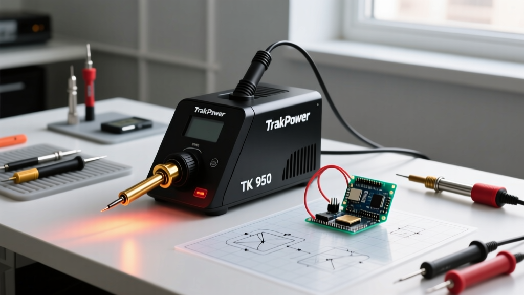

Introduction to the TrakPower TK-950 Architecture
The TrakPower TK 950 soldering station has long occupied a unique space in the electronics repair and DIY community. As a 48-watt digital station featuring a ceramic heating element and a push-button LED interface, it bridges the gap between cheap analog dial stations and high-end brushless RF systems. However, like many stations in the $70 to $95 price bracket, the TK-950 often ships from the factory with a thermocouple offset variance of up to ±15°C. For precision surface-mount device (SMD) work or sensitive through-hole components, this variance can lead to cold joints or thermal pad delamination.
This comprehensive tutorial will walk you through the proper ESD-safe setup, internal digital calibration, and thermal recovery optimization of your TrakPower TK 950 soldering station. By following these procedures, you will align your station's digital readout with the actual tip temperature, ensuring compliance with modern soldering standards.
Unboxing and Initial Hardware Setup
Before plugging the station into your mains supply, you must verify the physical integrity of the wand and the grounding path. The TK-950 utilizes a 4-wire ceramic heater wand terminated with a 5-pin DIN connector. The four internal wires carry the heater voltage (typically 24V AC) and the low-voltage thermocouple signal, while the DIN shell or a dedicated wire handles the earth ground.
Grounding and ESD Precautions
Electrostatic discharge (ESD) can instantly destroy modern CMOS and MOSFET components. The TK-950 includes a grounding wire with an alligator clip. Attach this to a verified earth ground point on your ESD mat or workbench. Using a digital multimeter (DMM), measure the resistance between the extreme tip of the soldering iron and the third prong (ground) of the station's AC plug. According to industry best practices, this resistance must read less than 2.0 ohms. If it reads higher, clean the tip collar and ensure the internal grounding spring inside the wand is making firm contact with the heater shaft.
The Calibration Process: Verifying Digital Accuracy
The digital display on the TK-950 is only as accurate as the thermocouple embedded in the ceramic heater. Over time, or even straight from the factory, thermal drift occurs. Calibrating the station requires comparing the LED readout against a known, high-accuracy external thermal probe.
Tools Required for Thermal Calibration
- External Thermometer: A K-type thermocouple meter with an accuracy of ±1°C or better.
- High-Temp Solder: 63/37 SnPb (Leaded) or SAC305 (Lead-Free) for thermal coupling.
- Ceramic Trimpot Screwdriver: To avoid shorting internal PCB components.
- Phillips #1 Screwdriver: For chassis removal.
Step-by-Step Internal Offset Adjustment
- Prepare the Tip: Install a standard 900M-B conical tip. Melt a generous blob of fresh solder onto the tip. This solder blob acts as a thermal bridge, ensuring accurate heat transfer to your external probe.
- Position the Probe: Bury the bead of your external K-type thermocouple directly into the molten solder blob on the tip.
- Set the Temperature: Power on the TK-950 and use the push buttons to set the digital display to exactly 350°C (662°F). Allow the station to cycle and stabilize for at least 3 minutes.
- Access the PCB: Unplug the unit, remove the four Phillips screws on the bottom chassis, and carefully lift the top shell. Rest the shell aside without straining the LED ribbon cable.
- Locate the Calibration Pot: Look for a small, multi-turn trim potentiometer on the main PCB, usually labeled CAL, TEMP, or VR1. It is typically located near the main comparator IC or the transformer.
- Adjust and Verify: Plug the unit back in. Using your ceramic screwdriver, make micro-adjustments (1/8th of a turn at a time) to the trimpot while watching your external K-type meter. Stop adjusting when the external meter reads exactly 350°C. The TK-950's digital display may now read slightly higher or lower than 350°C, but the actual physical tip temperature will be perfectly accurate.
Thermal Recovery and Tip Selection Matrix
A common mistake users make with the 48W TK-950 is pairing the wrong tip geometry with high-thermal-mass joints. The 48W ceramic heater recovers heat rapidly, but only if the tip's physical mass can transfer it to the copper pad. The NASA Workmanship Manual (NASA-STD-8739.3) emphasizes that proper wetting requires the pad and lead to reach the solder's liquidus temperature simultaneously, which is impossible if the tip geometry starves the joint of thermal energy.
| Tip Series (900M) | Geometry | Thermal Mass | Best Application |
|---|---|---|---|
| 900M-B | Conical (Fine Point) | Low | 0402/0603 SMD, delicate jumper wires |
| 900M-D | Chisel (1.6mm - 3.2mm) | High | Through-hole capacitors, thick ground planes |
| 900M-K | Knife (Angled) | Medium | Drag soldering QFPs, cleaning tight pads |
| 900M-C | Bevel (Hoof) | Medium-High | Large SMD connectors, tinning heavy wires |
As of 2026, replacement 900M-series tips for the TK-950 generally cost between $3 and $6 each, while replacement ceramic heater elements cost around $14 to $18. Always keep a spare heater element in your kit, as the brittle ceramic core can snap if the wand is dropped onto a hard floor.
Operational Best Practices & Fume Safety
When operating the TK-950 at lead-free SAC305 temperatures (typically 380°C+), the rapid degradation of rosin-based flux generates significant particulate and volatile organic compound (VOC) fumes. The National Institute for Occupational Safety and Health (NIOSH) explicitly warns that chronic exposure to rosin core solder fumes can cause occupational asthma and contact dermatitis.
Because the TK-950 does not feature an integrated fume extraction system, you must position an external ESD-safe fume extractor with a HEPA and activated carbon filter within 6 to 8 inches of the soldering zone. Never rely on a simple desk fan to blow fumes across your face; the airflow must be pulled away from your breathing zone and filtered.
Troubleshooting Common TK-950 Failure Modes
Even with meticulous calibration, digital stations can develop operational quirks. Here is how to diagnose the most frequent TK-950 issues:
1. Flashing Display or "H-E" Error Code
This indicates an open circuit in the heater or the thermocouple. Diagnostic Step: Unplug the station and disconnect the wand. Use a DMM to measure the resistance across the heater pins on the DIN plug (usually Pins 1 and 2). A healthy 48W/24V ceramic heater should read between 10 and 15 ohms. Next, measure the thermocouple pins (Pins 3 and 4); this should read near 0.0 ohms (a dead short). If the thermocouple reads infinite resistance, the ultra-thin sensor wires inside the silicone wand cord have snapped, requiring a full wand replacement.
2. Severe Tip Oxidation and Non-Wetting
If your tip turns black and solder rolls off in balls, the iron plating has oxidized. Never use sandpaper or a file to clean a 900M tip; you will destroy the microscopic iron layer and expose the copper core to rapid dissolution. Recovery Method: Set the TK-950 to a low temperature (250°C). Apply a massive amount of highly activated flux (like Amtech or MG Chemicals 8341) and aggressively rub the tip into a brass wool sponge while feeding fresh 63/37 leaded solder. The combination of chemical reduction and mechanical friction will usually restore the wetting layer.
3. Temperature Overshoot on Idle
If the station overshoots the set temperature by 20°C+ while resting in the holder, the internal TRIAC or solid-state relay on the main PCB may be failing in a "leaky" state, allowing continuous low-voltage current to reach the heater. This requires desoldering the TRIAC and replacing it with an equivalent component (such as a MAC97A8 or similar logic-level TRIAC, depending on the exact PCB revision).
Final Thoughts on the TK-950 Platform
The TrakPower TK 950 soldering station remains a highly capable tool for both hobbyists and professional repair technicians, provided it is properly calibrated and maintained. By taking the 15 minutes required to perform the internal trimpot calibration and selecting the correct tip geometry for your specific thermal loads, you elevate this 48W station from a basic DIY tool to a precision instrument capable of meeting IPC J-STD-001 workmanship requirements for Class 2 and Class 3 electronic assemblies.