
The Unmatched Utility of the Weller 25 Watt Soldering Iron
While high-end digital stations like the Weller WE1010 or Hakko FX-888D dominate professional electronics workbenches, the humble Weller 25 watt soldering iron—most notably the ubiquitous SP25NUS pencil model—remains an absolute powerhouse for field repairs, automotive wire splicing, and DIY through-hole PCB assembly. Priced consistently between $25 and $35 USD in 2026, this fixed-wattage tool offers a mechanical simplicity that forces the user to master fundamental thermal management techniques. Relying purely on thermal equilibrium rather than closed-loop active temperature control, the 25W Weller iron demands respect and precise handling. In this comprehensive technique guide, we will break down the exact metallurgical and thermal strategies required to produce IPC-compliant solder joints using this classic instrument.
The 25W Sweet Spot: A 25-watt iron provides enough thermal mass to melt standard 60/40 Sn/Pb solder on 22 AWG wire without instantly vaporizing flux or scorching FR4 fiberglass substrates. It is the ultimate bridge between low-wattage precision craft irons and high-wattage plumbing tools.Thermal Dynamics: Managing Fixed-Wattage Recovery
To master the Weller 25 watt soldering iron, you must first understand its thermal profile. Unlike a T12 or WSP80 handpiece that uses a thermocouple and microcontroller to pump precise wattage into the tip the millisecond it detects a temperature drop, the SP25NUS relies on a continuous 25-watt nichrome heating element. When idling in its stand, the tip crests at approximately 450°C (842°F).
When you apply the tip to a copper pad or a thick wire, the joint acts as a heat sink, rapidly pulling thermal energy away from the iron. The 25W heater requires roughly 8 to 12 seconds to recover its idle temperature after a heavy joint. Therefore, the golden rule of fixed-wattage soldering is the 3-Second Dwell Limit. If a joint requires more than 3 seconds of direct heat to achieve flow, your technique, tip selection, or solder gauge is incorrect. Prolonged contact will not make the iron 'hotter'; it will only result in flux burnout, severe oxidation, and catastrophic pad delamination on printed circuit boards.
Tip Selection Matrix for 25W Applications
The Weller SP series utilizes the legendary ETA screw-on tip system. Selecting the correct thermal mass for your specific joint is the single most critical decision you will make. A tip that is too small will stall and freeze to the joint; a tip that is too large will transfer heat too aggressively, risking component damage.
| Tip Model | Geometry | Best Application | Thermal Mass |
|---|---|---|---|
| ETS | 1/64" Conical | Fine pitch SMD, 26-28 AWG wire | Low (High oxidation risk) |
| ETA | 1/32" Conical | Standard through-hole, 24 AWG | Medium-Low |
| ETB | 1/16" Conical | Heavy through-hole, 22 AWG splicing | Medium |
| ETD | 1/8" Screwdriver | Ground planes, thick gauge lugs | High |
Step-by-Step Technique: Soldering 22 AWG Stranded Wire
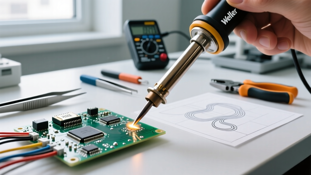
Splicing 22 AWG stranded wire is the most common task for the Weller 25 watt soldering iron. According to the NASA Workmanship Standards for soldered connections, a proper wire splice requires complete wetting and a visible contour of the wire strands beneath the solder fillet.
- Preparation: Strip exactly 1/4 inch (6.35mm) of insulation from both wire ends. Mechanically twist the strands tightly to prevent fraying.
- The Pre-Tin: Apply a small amount of 60/40 Sn/Pb rosin-core solder (0.031" diameter) directly to the twisted wires using the iron. Do this for both wires independently. The flux will activate at 150°C, cleaning the copper oxide, while the 183°C eutectic solder flows into the capillary gaps.
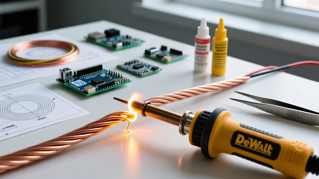
- The Mechanical Lock: Cross the pre-tinned wires in an 'X' shape and twist them together using needle-nose pliers to create a mechanical bond before the soldering iron even touches the joint.
- The Reflow: Apply the ETB tip to the side of the twisted joint for exactly 1.5 seconds. The pre-existing solder will melt and fuse the wires into a single monolithic conductor.
- Cooling: Remove the iron and hold the wires perfectly still for 3 seconds. The solder will transition from liquid to solid. Any movement during this phase change will result in a disturbed, grainy joint.
Step-by-Step Technique: Through-Hole PCB Assembly
When transitioning to printed circuit boards, the thermal dynamics change drastically. The copper pad on an FR4 board is bonded with epoxy resin that begins to degrade and delaminate if exposed to temperatures exceeding 260°C for more than a few seconds. The SparkFun Through-Hole Soldering Guide emphasizes the importance of simultaneous heating.
- Flux Application: Even if using rosin-core solder, applying a drop of liquid tacky flux (such as Amtech or MG Chemicals 8341) to the via ensures immediate wetting and reduces the required dwell time.
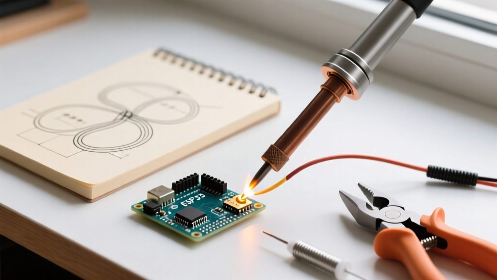
- The 45-Degree Approach: Hold the Weller 25W iron like a pencil. Approach the joint at a 45-degree angle so the flat of the conical tip touches both the component lead and the copper pad simultaneously. This is critical; heating only the lead will result in a cold joint.
- The Count: Mentally count "one-mississippi, two-mississippi."
- Feed the Solder: Touch your 0.031" solder wire to the opposite side of the joint, directly across from where the iron is resting. If the iron has heated the joint correctly, the solder will instantly melt and be drawn into the via by capillary action.
- The Retreat: Once the solder forms a concave fillet (resembling the inside of a volcano), remove the solder wire first, then pull the iron away at a sharp upward angle to prevent solder spikes.
Troubleshooting Common 25W Failure Modes
Because the Weller 25 watt soldering iron lacks digital feedback, visual and tactile cues are your only diagnostic tools. Consult the IPC J-STD-001 Standards for defect identification, and use the matrix below to correct your technique.
| Failure Mode | Visual Symptom | Root Cause | Corrective Action |
|---|---|---|---|
| Non-Wetting (Beading) | Solder rolls off the pad into a ball | Severe tip oxidation or flux burnout | Clean tip in brass wool, apply fresh liquid flux, re-tin immediately |
| Disturbed Joint | Dull, grainy, or frosty appearance | Component moved during the 2-second solidification phase | Reheat the joint fully with added flux and hold completely still until cool |
| Pad Delamination | Copper pad lifts off the green FR4 substrate | Dwell time exceeded 4 seconds; tip too small | Switch to an ETD chisel tip for faster thermal transfer; use pre-flux |
| Solder Wicking | Solder climbs up the lead away from the board | Heating the lead instead of the pad | Focus 80% of the tip surface area on the PCB pad, 20% on the lead |
Maintenance: Why the Damp Sponge is the Enemy of 25W Irons
Most entry-level kits include a damp cellulose sponge for tip cleaning. For a 70W digital station, wiping a hot tip on a wet sponge is fine. For a Weller 25 watt soldering iron, this practice is detrimental. The sudden thermal shock of the damp sponge drops the tip temperature by over 100°C instantly. Because the 25W nichrome heater recovers slowly, the tip sits at a sub-optimal temperature for nearly 15 seconds. During this recovery window, any residual flux carbonizes onto the iron, creating a hard, black oxide layer that completely repels molten solder.
The Expert Alternative: Discard the sponge. Use a dry brass wool tip cleaner (often sold as a 'brass sponge'). Brass is softer than the iron and copper plating of the ETA tip, so it will not scratch the protective coating, but it is highly conductive and mechanically abrasive enough to shear off oxidized flux residue without dropping the core temperature of the tip. Always finish your soldering session by melting a generous blob of 60/40 rosin-core solder over the entire working surface of the tip before turning off the power. This sacrificial layer of solder will oxidize while the iron cools, protecting the actual iron plating underneath until your next project.