
The Hidden Cost of Thermal Drift in Modern Electronics
When working with sensitive CMOS components, fine-pitch QFN packages, or multi-layer RF boards, relying on the factory LCD readout of your temp soldering iron is a dangerous gamble. A station displaying 350°C on its digital screen might actually be pushing 385°C at the physical tip due to sensor degradation, ambient temperature shifts, or manufacturing tolerances. According to the IPC J-STD-001 standard for soldered electrical assemblies, maintaining strict thermal profiles is critical to preventing pad delamination, tombstoning, and latent thermal damage to silicon dies.
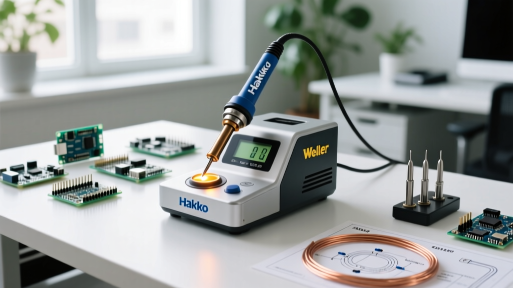
In 2026, with the widespread adoption of lead-free SAC305 solder alloys and high-thermal-mass server motherboards, precise temperature control is non-negotiable. This tutorial provides a masterclass in setting up and calibrating the most popular digital temp soldering iron stations on the market: the Hakko FX-888D, the Weller WE1010NA, and the open-source RISC-V powerhouse, Pinecil V2.
The Physics of Thermal Offset and Sensor Degradation
Why do digital soldering stations drift from their factory calibration? The answer lies in the harsh operating environment of the tip assembly. Most modern stations utilize a K-type thermocouple embedded directly inside the ceramic heating element or the tip sleeve itself. Over hundreds of heating and cooling cycles, the metallurgical structure of the thermocouple wires undergoes microscopic changes. The constant exposure to temperatures exceeding 400°C causes the alloy grains to grow, subtly altering the electrical resistance and the resulting Seebeck voltage output.
Furthermore, the physical mating surface between the heating element and the tip sleeve is critical. Even a microscopic layer of oxidized flux residue or airborne dust acts as a thermal insulator. If the station's microcontroller reads a 350°C signal, but a thermal bottleneck exists at the tip collar, the actual working face of the tip might only be 315°C. This discrepancy leads to cold solder joints, poor wetting, and the temptation to crank the station up to 420°C—which only accelerates tip oxidation and destroys the flux core in your solder wire before it even touches the pad.
Essential Calibration Toolkit
You cannot calibrate a sensor without a higher-trust reference. Do not use cheap infrared thermometers; they measure surface emissivity and will give you wildly inaccurate readings on shiny, metallic soldering tips. Instead, assemble the following toolkit:
- Tip Thermometer: The Hakko FG-100B (approx. $145) is the industry standard. Alternatively, use a bare K-Type thermocouple bead paired with a calibrated Fluke 87V multimeter.
- Tip Cleaner: Brass wire sponge. Never use wet cellulose sponges during calibration, as the rapid quenching skews thermal equilibrium and shocks the ceramic heating element.
- Reference Solder: Sn63/Pb37 (Eutectic) wire with a rosin core. Eutectic solder has a sharp, exact melting point of 183°C, making it perfect for verifying low-end thermal accuracy.
IPC Temperature Standards Reference Matrix
Before adjusting your temp soldering iron, you must know your target. The following matrix aligns with general Adafruit and industry best practices for modern PCB assembly:
| Component / Task Type | Recommended Tip Temp | Max Dwell Time | Preferred Tip Geometry |
|---|---|---|---|
| 0402 / 0201 SMD Passives | 300°C - 320°C | 1.5 - 2 Seconds | Micro Pencil (0.4mm) |
| Standard DIP / SOIC ICs | 330°C - 350°C | 3 - 4 Seconds | Chisel (1.6mm - 2.4mm) |
| Heavy Ground Planes / XT90 | 380°C - 400°C | 5 - 7 Seconds | Wide Chisel / Hoof (4mm+) |
| Desoldering TH Components | 360°C - 380°C | As needed w/ flux | Desoldering Gun Tip |
Step-by-Step Calibration: Hakko FX-888D
The Hakko FX-888D remains a bench staple in 2026, retailing around $115. However, its T18 tip thermocouples are prone to drift after 400+ hours of use. Here is how to recalibrate the internal ADC (Analog-to-Digital Converter) offset.
- Reach Thermal Equilibrium: Turn on the station and set it to 350°C. Let it sit idle for exactly 5 minutes. The thermal mass of the heater and tip must stabilize.
- Measure the Actual Temperature: Fold the brass wire sponge over the tip to ensure a solid physical connection, or use a specialized tip holder. Insert the FG-100B thermocouple sensor directly onto the tinned working surface of the tip. Wait 15 seconds for the reading to lock.
- Enter Calibration Mode: Turn the station OFF. Press and hold the UP arrow button, then turn the power ON. The display will show a blinking value (the current offset).
- Adjust the Offset: If your LCD reads 350°C but the FG-100B reads 338°C, you must input 338 into the station. Use the UP and DOWN arrows to match the LCD to your external thermometer.
- Save and Exit: Press and hold the UP arrow for 2 seconds until the display stops blinking. The station is now calibrated to the physical reality of that specific T18 tip.
Step-by-Step Calibration: Weller WE1010NA
The Weller WE1010NA (approx. $130) features a slightly different menu architecture but relies on the same fundamental thermocouple principles. Weller's ET and XT tips are renowned for their rapid thermal recovery, but they still require periodic verification.
- Access the Hidden Menu: With the station powered on, press and hold the + and - buttons simultaneously for about 3 seconds until the display enters the setup parameters.
- Navigate to Offset: Use the buttons to scroll through the menu options until you reach the 'Temperature Offset' parameter.
- Measure and Compare: Just like the Hakko method, ensure the iron has idled for 5 minutes. Measure the tip with your FG-100B.
- Apply the Delta: If the Weller reads 350°C and your external meter reads 342°C, you need to apply an offset of -8°C. Adjust the value in the menu accordingly.
- Confirm and Exit: Press the main selector knob or hold the button combination again to save the EEPROM data and return to the main operational screen.
Step-by-Step Calibration: Pinecil V2 (RISC-V)
The Pinecil V2 (approx. $30) has disrupted the market with its open-source IronOS firmware and RISC-V architecture. Because it uses T12-style tips with integrated thermocouples, calibration is handled via software menus.
- Boot into Settings: Power on the Pinecil and immediately press the main button to enter the settings menu.
- Navigate to Calibration: Scroll to Settings > Calibration > Calibrate Tip. Detailed documentation for this can be found in the Pine64 Pinecil Wiki.
- Heat to Target: The firmware will prompt you to heat the iron to a specific high temperature (usually around 300°C or 400°C).
- Input External Reading: Once the Pinecil indicates it has reached the target, measure the tip with your K-Type thermocouple. Enter the exact external measurement into the Pinecil using the buttons.
- Flash the Offset: The IronOS firmware will automatically calculate the ADC voltage offset and save it to the EEPROM. Repeat this process if you swap to a different tip model, as each tip's internal thermocouple has unique resistance characteristics.
Troubleshooting Edge Cases & Sensor Failures
Even after following the correct calibration procedure, you may encounter erratic behavior. Here is how to diagnose hardware-level failures in your temp soldering iron setup:
1. Erratic Temperature Swings (±20°C)
Failure Mode: This is rarely a calibration issue. It usually indicates a fractured thermocouple wire inside the ceramic heater sleeve or severe oxidation on the tip's mating surface.
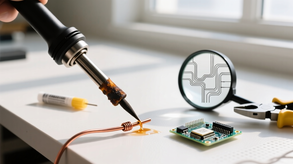
Solution: Remove the tip and inspect the metal collar. If you see black, flaky oxidation, clean it with a fiberglass scratch pen. If the issue persists, the internal thermocouple junction is compromised, and the tip must be replaced.
2. Slow Thermal Recovery on Large Pads
Failure Mode: The iron reads the correct temperature, but drops 50°C the moment it touches a ground plane.
Solution: This is a wattage and thermal mass limitation, not a calibration error. A 65W Hakko FX-888D simply cannot replenish heat fast enough into a 10-layer motherboard ground plane. You must switch to a high-wattage station (like a 150W Weller WXD2) or use PCB pre-heating techniques.
3. Ground Loop Interference
Failure Mode: When soldering live circuits or audio equipment, the digital display flickers or the heater shuts off unexpectedly.
Solution: Ensure your soldering station is connected to a properly grounded 3-prong AC outlet. Ungrounded setups allow EMI (Electromagnetic Interference) to couple into the low-voltage thermocouple signal wires, confusing the station's microcontroller.
Pro Tip for 2026: Always calibrate your station with the specific tip installed. A Hakko T18-B (conical) and a T18-D24 (chisel) have different thermal masses and thermocouple placement depths. Calibrating for one will introduce a slight offset when switching to the other.
Final Thoughts on Precision Soldering
Calibrating your temp soldering iron is not a one-time setup task; it is a routine maintenance procedure. For professional labs adhering to ISO 9001 or IPC standards, tip calibration should be logged monthly. For hobbyists and DIY repair technicians, recalibrating every time you open a new box of tips or change your primary tip geometry will drastically reduce collateral thermal damage to your PCBs. By understanding the physics of thermal transfer and utilizing the correct diagnostic tools, you transform your soldering station from a blunt heating tool into a precision surgical instrument.