
The Anatomy of a Modern DIY Soldering Iron
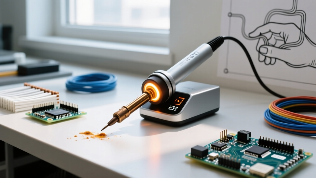
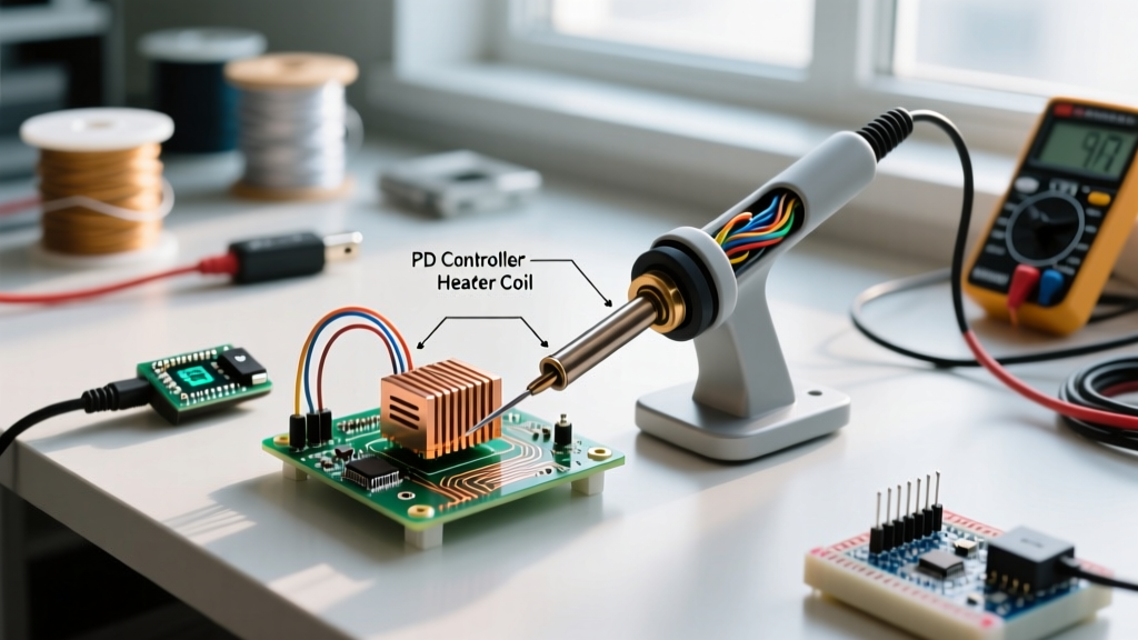
While commercial stations like the Hakko FX-951 or portable smart irons like the Pinecil V2 dominate the market, building a DIY soldering iron remains a rite of passage for serious electronics engineers. In 2026, the proliferation of USB-C Power Delivery (PD 3.1) chargers capable of outputting 100W to 140W has completely transformed the DIY soldering landscape. You no longer need heavy, line-powered transformers. By combining a USB-C PD decoy module with a high-efficiency T12 cartridge heater, you can engineer a custom iron tailored to your exact ergonomic and thermal requirements.
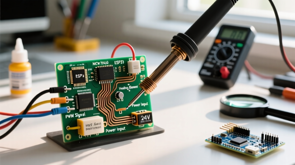
This technique guide bypasses the basic 'resistor-hack' tutorials and dives deep into engineering a digitally controlled, USB-C powered DIY soldering iron using a T12 heating element, a zero-drift operational amplifier, and a 32-bit microcontroller for precise Pulse Width Modulation (PWM) thermal management.
Bill of Materials (BOM) & Component Selection
To achieve professional-grade thermal recovery, we must select components that minimize latency and maximize power transfer. Below is the engineered BOM for a 100W-capable DIY rig.
| Component | Model / Specification | Estimated Cost (2026) | Engineering Purpose |
|---|---|---|---|
| Heater Cartridge | Hakko T12-D24 (or KSGER clone) | $14.00 - $18.00 | Integrated 8Ω heater and K-type thermocouple. |
| PD Trigger | IP2721 USB-C PD Decoy Board | $3.50 | Negotiates 20V @ 5A (100W) from PD bricks. |
| Op-Amp | Texas Instruments OPA333 | $2.80 | Zero-drift, low-offset amplification for µV thermocouple signals. |
| Microcontroller | STM32G030 (ARM Cortex-M0+) | $1.50 | Handles ADC sampling, PID math, and PWM generation. |
| MOSFET | IRLZ44N (Logic Level) | $1.20 | Drives the 2.5A+ heater load with minimal Rds(on) heat. |
Circuit Design: The Thermocouple Sampling Challenge
The most critical failure point in amateur DIY soldering iron designs is the inability to read the tip temperature accurately. The T12 cartridge places the K-type thermocouple and the nichrome heater in series. You cannot measure the thermocouple's microvolt output while current is flowing through the heater.
The PWM Off-Cycle Sampling Technique
To solve this, your microcontroller must implement synchronized ADC sampling. According to thermocouple reference tables from the NIST Thermocouple Database, a K-type thermocouple generates approximately 41 µV per °C. At 350°C, the output is roughly 14.3 mV.
- Drive Phase: The STM32 outputs a PWM signal to the IRLZ44N MOSFET gate, energizing the 8Ω heater.
- Sampling Phase: The MCU pulls the PWM pin LOW, cutting power to the heater.
- Settling Delay: Wait 50–100 microseconds for the inductive kickback from the heater coil to dissipate.
- ADC Read: Trigger the ADC to read the voltage across the OPA333 differential amplifier stage.
Running this loop at 20Hz ensures the human eye perceives continuous heating, while the MCU gathers 20 temperature samples per second to feed the PID algorithm. For advanced signal conditioning design, the Texas Instruments Application Note (SLYT271) provides excellent schematics for minimizing noise in low-level thermocouple amplification.
Thermal Calibration & PID Tuning Techniques
A common mistake when building a DIY soldering iron is relying on simple bang-bang (on/off) control, which causes severe temperature oscillation and oxidizes the tip. You must implement a Proportional-Integral-Derivative (PID) controller.
Expert Calibration Tip: Soldering tips have non-linear thermal mass. A thick chisel tip (T12-D24) requires aggressive Derivative (D) gain to prevent overshoot when it contacts a cold ground plane, whereas a micro-pencil tip (T12-IL) requires higher Proportional (P) gain to maintain baseline heat. Never use a single PID profile for all tips.
To tune your DIY iron, perform a step-response test:
- Set the target temperature to 300°C and log the thermocouple ADC values via UART.
- If the temperature overshoots 320°C before settling, increase your Derivative coefficient.
- If the temperature takes more than 8 seconds to reach 300°C without overshooting, increase your Proportional coefficient.
- Use the Ziegler-Nichols method to find the ultimate gain (Ku) and oscillation period (Tu), then calculate your baseline Kp, Ki, and Kd values.
Technique Guide: Soldering with a Custom USB-C Rig
Once your hardware and firmware are calibrated, the physical technique of using a high-wattage USB-C DIY iron differs slightly from traditional bench stations.
1. Managing USB-C PD Power Limits
Even if your PD brick is rated for 100W, continuous 100W draw will trigger thermal throttling in most GaN chargers within 45 seconds. Your firmware should implement a 'boost mode' that allows 100W draw for exactly 5 seconds when a rapid temperature drop is detected (indicating contact with a large copper pour), before tapering back to a sustainable 65W baseline.
2. ESD and AC Leakage Mitigation
Unlike traditional irons that use isolated 24V AC transformers, USB-C chargers are switch-mode power supplies that can leak high-frequency AC voltage to the DC ground. If you touch a sensitive MOSFET gate or bare die with a DIY iron connected to an ungrounded laptop charger, the AC leakage can destroy the component.
Solution: Always use a USB-C PD charger with a 3-prong grounded AC plug. Verify with a multimeter that the AC voltage between your iron's tip and a known earth ground is less than 50mV RMS. If it exceeds this, add an equipotential bonding wire from the iron's metal tip sleeve to your bench's ESD grounding jack.
3. Tip Maintenance to IPC Standards
According to the IPC J-STD-001 requirements for soldered assemblies, proper wetting and thermal transfer are critical for reliable intermetallic compound (IMC) formation. Because DIY irons can suffer from minor calibration drift over time, always use a brass wire sponge rather than a wet sponge. A wet sponge causes a rapid thermal shock that drops the tip temperature by up to 40°C, forcing your PID loop into saturation and degrading the iron plating over time.
Critical Failure Modes & Troubleshooting
When your DIY build misbehaves, refer to this diagnostic matrix:
- Symptom: Iron heats to maximum and glows red, ignoring set temperature.
Cause: Broken thermocouple wire inside the T12 cartridge, or OPA333 output saturated. The MCU reads 0V and drives PWM to 100%. Fix: Replace cartridge; check Op-Amp feedback resistor network. - Symptom: PD Trigger clicks repeatedly, iron resets.
Cause: Inrush current tripping the PD brick's over-current protection (OCP). Fix: Add a 470µF low-ESR capacitor across the 20V rail and implement a soft-start routine in firmware that ramps PWM from 0% to 50% over 500ms. - Symptom: Solder joints appear dull and grainy (cold joints).
Cause: Thermocouple cold-junction compensation (CJC) error. The OPA333 is reading the tip relative to ambient room temperature, not 0°C. Fix: Integrate an I2C temperature sensor (like the TMP117) near the T12 connector to add ambient CJC offset to your ADC readings.
Conclusion
Building a DIY soldering iron using USB-C PD and T12 technology is more than a weekend project; it is a masterclass in power electronics, thermodynamics, and embedded systems control. By mastering the PWM off-cycle sampling technique and properly tuning your PID loops, you can create a custom soldering tool that rivals $300 commercial stations, all powered by a charger that fits in your pocket.