
The Anatomy of a Professional SMD Soldering Rework Station
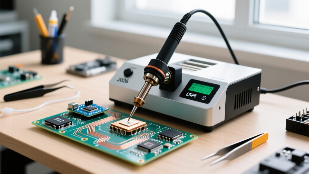
Transitioning from through-hole soldering to surface-mount device (SMD) rework requires a fundamental shift in thermal management. While a basic hot air pencil might suffice for swapping a simple SOIC-8 chip, tackling modern high-density boards demands a true SMD soldering rework station. In 2026, professional stations like the Quick 861DW+, Hakko FR-830, and JBC JTSE dominate the market by offering closed-loop temperature control, brushless micro-fans for precise airflow, and programmable thermal profiles.
A professional rework station does not merely blow hot air; it manages thermal mass. The core difference lies in the sensor placement and feedback loop. High-end stations measure the temperature at the nozzle exit and adjust the heating element in milliseconds to compensate for the cooling effect of high airflow rates. This ensures that when you are reflowing a large ground plane, the air temperature remains stable rather than plummeting.
Thermal Profiling: Nozzle vs. Junction Temperature
The most common mistake technicians make is confusing the station's displayed nozzle temperature with the actual solder junction temperature on the PCB. According to IPC rework standards, the goal is to bring the solder alloy above its liquidus state (e.g., 217°C for SAC305 lead-free solder) without exceeding the component's maximum thermal rating, typically 245°C for 10 seconds.
To achieve this, you must account for thermal lag. If your station reads 360°C, the actual pad temperature on a 4-layer PCB with heavy copper pours might only be 200°C. This is why preheating is non-negotiable for complex rework. Using an IR or ceramic bottom preheater to bring the entire board to 120°C - 140°C reduces the thermal delta, allowing your SMD soldering rework station to finish the job at lower airflow and temperature settings, thereby preventing pad lifting and component warpage.
Component Airflow and Temperature Matrix
Airflow, measured in liters per minute (L/min), is just as critical as temperature. Too much airflow on a 0402 resistor will blow it off the pad; too little on a 10x10mm QFN will result in cold solder joints on the inner thermal pad. Use the following matrix as a baseline for your station profiles:
| Component Type | Nozzle Temp (Lead-Free) | Airflow (L/min) | Nozzle Style | Preheat Required? |
|---|---|---|---|---|
| 0402 / 0603 Passives | 320°C - 340°C | 5 - 10 L/min | Small Round / Bent | No |
| SOIC / TSSOP (Fine Pitch) | 340°C - 360°C | 15 - 25 L/min | Wide Rectangular | Recommended |
| QFN-32 to QFN-64 | 360°C - 380°C | 30 - 45 L/min | Square (Component specific) | Yes (120°C board temp) |
| BGA (Ball Grid Array) | 370°C - 400°C | 40 - 60 L/min | Large Round / BGA Specific | Mandatory (140°C+) |
Step-by-Step Technique: QFN-32 Removal and Replacement
Quad Flat No-lead (QFN) packages are notorious for hiding their connections beneath the package body, making visual inspection of solder joints difficult. Here is the definitive technique for QFN rework using a modern SMD soldering rework station.
- Flux Application: Apply a generous amount of high-tack, no-clean flux (such as Amtech NC-559-V2-TF or Kester 245) around the perimeter of the QFN. The flux acts as a heat transfer medium and prevents oxidation during the extended heating cycle.
- Targeted Preheating: If you do not have a bottom preheater, use a wide-nozzle hot air gun at 200°C and 50 L/min to gently warm the surrounding 2-inch area of the PCB for 45 seconds.
- Reflow for Removal: Switch to a square nozzle that closely matches the QFN dimensions. Set your station to 370°C and 35 L/min. Hold the nozzle 10mm above the IC, moving in slow, concentric circles. After 20-30 seconds, gently nudge the IC with fine-point titanium tweezers. When it slides freely, the solder has reached liquidus. Lift it straight up.
- Pad Preparation: Clean the pads using 2.0mm desoldering braid (Chemtronics Soder-Wick) and a high-quality soldering iron set to 350°C. The pads must be perfectly flat and shiny. Clean with 99% isopropyl alcohol (IPA).
- Placement and Reflow: Apply a thin, even layer of flux to the pads. Place the new QFN using a vacuum pickup tool, aligning the pin-1 indicator. Apply hot air at 360°C and 30 L/min. Watch for the 'self-centering' effect where surface tension pulls the chip into perfect alignment as the solder melts.
Advanced BGA Rework: Managing Thermal Mass and Warpage
Ball Grid Array (BGA) rework is where the true capability of an SMD soldering rework station is tested. Because the solder joints are entirely hidden, you are relying entirely on thermal physics and profile timing.
Pro-Tip from the Bench: Never attempt BGA removal on a multi-layer board with heavy ground planes without a dedicated bottom preheater. The top-side hot air will scorch the component and delaminate the PCB fiberglass before the inner solder balls ever reach 217°C.
When reworking BGAs, the primary failure mode is popcorning or substrate warpage. This occurs when the top of the BGA heats significantly faster than the bottom, causing the plastic substrate to bend and snap the solder balls. To prevent this, your bottom preheater must account for at least 60% of the total thermal energy required. The top air from your rework station should only provide the final 40% to push the junction over the reflow threshold.
For reballing, use a stencil matched to the BGA pitch (e.g., 0.5mm or 0.8mm) and Type 4 or Type 5 solder paste for the finest pitches. As highlighted in the NASA NEPP Soldering Guidance documentation, ensuring consistent solder volume across all hundreds of microscopic pads is critical to preventing open circuits or bridging under the BGA footprint.
Troubleshooting Common Rework Failures
Even with a premium SMD soldering rework station, technique flaws will yield defective boards. Use this troubleshooting guide to diagnose your failures:
- Tombstoning on Passives: Caused by uneven heating. If one pad reaches reflow temperature before the other, the surface tension of the molten solder will pull the component upright. Fix: Use a wider airflow pattern and heat both pads simultaneously, or ensure your PCB preheat is adequate.
- Pad Cratering / Lifting: Occurs when excessive mechanical force is applied with tweezers before the solder is fully molten, or when the station temperature is set too low, requiring prolonged heating that degrades the FR4 epoxy. Fix: Increase airflow rather than temperature to transfer heat faster, and never force a component off the board.
- Solder Balls Under BGA: Usually the result of flux boiling and splattering, or using a solder paste with an aggressive solvent profile. Fix: Switch to a low-spatter, halogen-free flux and ensure the board is completely free of moisture by baking it at 100°C for 2 hours prior to rework.
- Cold Joints on QFN Thermal Pads: The large ground pad beneath the QFN acts as a massive heatsink. Fix: You must apply heat from the bottom of the PCB directly under the component, or use a station with a high thermal recovery rate to sustain the energy transfer through the board layers.
Final Thoughts on Station Selection
Investing in a high-quality SMD soldering rework station is an investment in yield. While entry-level $80 stations rely on basic triac dimmers and lack airflow sensors, modern $400-$800 units utilize digital mass airflow sensors and PID controllers. When working on 2026-era electronics featuring dense 0201 components and high-I/O BGAs, the precision of your air and heat delivery is the only thing standing between a successful repair and a scrapped motherboard.