
The 'Silver Solder' Misconception: Iron vs. Torch
When hobbyists and technicians begin troubleshooting soldering iron silver solder failures, the root cause is frequently a fundamental misunderstanding of metallurgy. The term 'silver solder' is colloquially used to describe two entirely different processes: hard silver brazing and soft silver-bearing electronics soldering. If your soldering iron is failing to melt the silver wire you purchased, you are likely attempting to use a soft-soldering tool on a hard-brazing alloy.
Hard Silver Brazing (Jewelry, Plumbing, HVAC)
True hard silver solder (often containing 15% to 45% silver, such as Harris Stay-Silv 45) is a brazing alloy. It requires temperatures between 1,100°F and 1,300°F (593°C to 704°C) to reach its liquidus state. No standard 60W to 80W electronics soldering iron can achieve this thermal output. If you apply an iron to hard silver solder, the flux will burn into a hard black crust, the alloy will remain solid, and the base metal will oxidize. Solution: Put down the soldering iron and use an oxy-acetylene, propane, or MAPP gas torch.
Soft Silver-Bearing Solder (Electronics & PCBs)
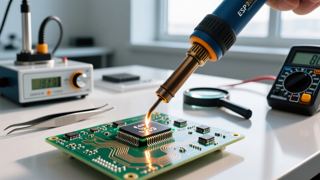
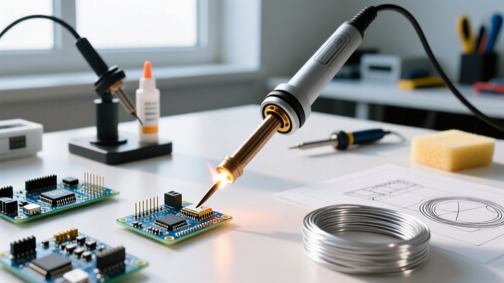
In the electronics industry, 'silver solder' refers to lead-free alloys that contain a small percentage of silver to improve mechanical strength and thermal fatigue resistance. The most common is SAC305 (96.5% Tin, 3.0% Silver, 0.5% Copper). As of 2026, with RoHS compliance strictly enforced globally, SAC305 remains the industry standard, with 1lb spools of 0.031-inch wire typically costing between $65 and $85. This alloy melts at 217°C (422°F), which is well within the capabilities of a modern soldering station, but it introduces unique troubleshooting challenges regarding wetting, thermal recovery, and tip degradation.
Troubleshooting Electronics Silver Solder (SAC305) Melting Issues
If you are using SAC305 or a similar silver-bearing alloy (like Sn95.5/Ag3.8/Cu0.7) and experiencing poor wetting, dull joints, or cold solder connections, the issue is almost always thermal mismanagement. Silver-bearing alloys have a higher surface tension and a narrower plastic (pasty) range than traditional Sn63/Pb37 leaded solder.
Expert Insight: According to the IPC J-STD-001 standards for soldered electrical assemblies, a proper SAC305 joint should exhibit a smooth, bright, and concave fillet. A dull, grainy, or disturbed joint indicates that the assembly moved during the alloy's narrow solidification phase or that the flux was exhausted before adequate wetting occurred.
Optimizing Station Temperatures for Silver Alloys
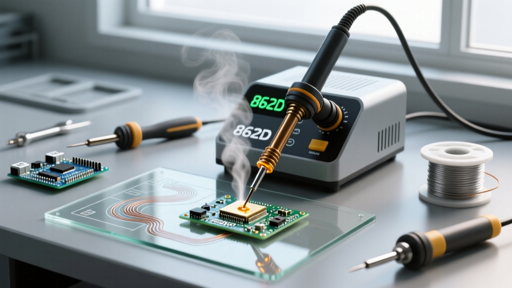
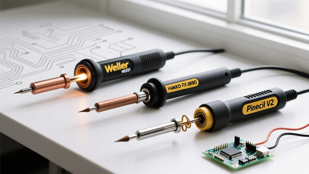
Do not set your station to the exact melting point of the alloy. To achieve proper capillary action and flux activation, your tip temperature must be significantly higher. For standard PCB work with SAC305, set your station between 350°C and 380°C (662°F to 716°F). If you are soldering to large ground planes, you may need to push to 400°C, but only if using a high-thermal-mass tip and a station with rapid thermal recovery, such as the Hakko FX-951 or Weller WE1010NA.
| Symptom | Root Cause | Corrective Action |
|---|---|---|
| Solder balls up and refuses to wet the pad | Tip temperature too low; flux not activated. | Increase station temp by 20°C. Apply fresh ROL1 no-clean flux. |
| Joint is dull, grainy, or rough | Disturbed joint during solidification or oxidized alloy. | Hold the component perfectly still for 2-3 seconds post-heat. Clean the tip. |
| Pad lifts off the PCB | Excessive dwell time due to undersized tip. | Switch to a chisel or bevel tip (e.g., Hakko T18-D24) to maximize surface contact area. |
| Solder climbs the iron tip, not the lead | Tip is oxidized or flux is depleted. | Use a brass wire sponge and apply a high-activity tip tinner immediately. |
Tip Degradation: Why Silver Alloys Eat Your Iron Tips
The most frequent maintenance complaint when transitioning to silver-bearing solders is rapid tip erosion. To understand why this happens, we must look at the metallurgical composition of a modern soldering iron tip. According to technical data from Indium Corporation and major tip manufacturers, a standard tip consists of a high-conductivity copper core, plated with a 100 to 150-micron layer of iron to prevent the molten tin from dissolving the copper. The very end of the tip is then plated with tin to allow for initial wetting.
The Scavenging Effect
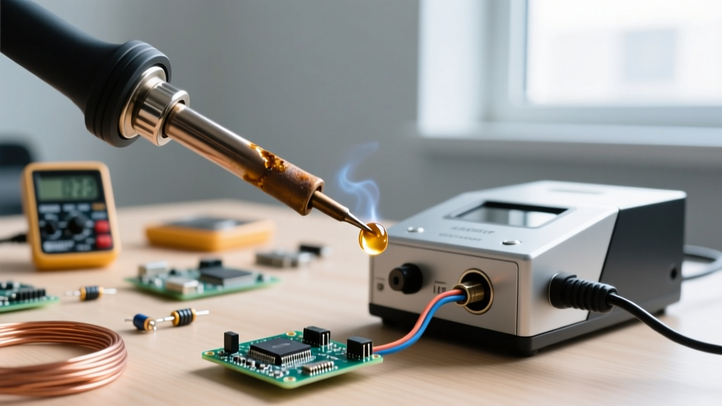
When you use a silver-bearing, lead-free alloy like SAC305, the molten tin in the solder aggressively seeks out more tin and iron to reach equilibrium. Because the silver and copper in the alloy do not readily dissolve the iron plating, the tin in the SAC305 'scavenges' the iron layer on your tip at a rate up to three times faster than traditional leaded solder. Once the iron plating is breached, the molten solder dissolves the underlying copper core, resulting in deep pitting, cratering, and total tip failure.
Step-by-Step Tip Maintenance Protocol for SAC Alloys
To extend the life of your $10 to $15 replacement tips when working with silver alloys, implement this strict maintenance protocol:
- Never Idle at High Heat: Leaving a station at 380°C while not actively soldering accelerates oxidation and iron scavenging. Always use your station's auto-sleep feature to drop the temperature to 200°C when the iron is holstered.
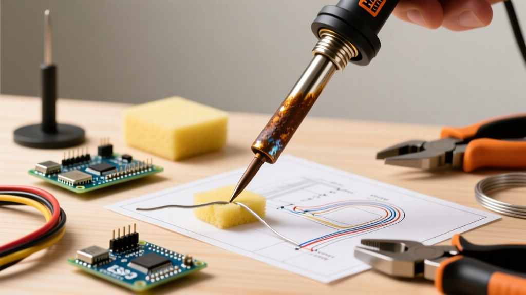
- Use a Brass Wire Sponge: Avoid wet cellulose sponges. The thermal shock of a wet sponge drops the tip temperature drastically, causing the iron plating to micro-crack, which allows the silver-bearing solder to penetrate and destroy the copper core.
- Re-Tin Immediately After Use: Before turning off your station, melt a generous blob of fresh SAC305 (or a dedicated tip-tinning compound like Hakko 599B) onto the working end of the tip. This sacrificial layer oxidizes in the air, protecting the underlying iron plating.
- Rotate High-Mass Tips: For heavy ground-plane work, rotate between two high-mass chisel tips (e.g., Weller RTW2 or JBC C245-903) to allow the iron plating to 'rest' and cool, reducing the cumulative thermal stress.
Flux Chemistry and Silver Tarnish Troubleshooting
Silver-bearing alloys require more aggressive flux chemistries to break down the tenacious oxides that form at higher soldering temperatures. Standard mildly activated rosin (RMA) fluxes often fail to provide the wetting action required for SAC305.
Selecting the Right Flux
For troubleshooting poor wetting on silver-alloy joints, upgrade to a ROL0 or ROL1 (Rosin, Low Activity) no-clean flux, or a water-soluble ORH1 (Organic, High Activity) flux if your assembly process includes an aqueous cleaning step. Gel fluxes containing a higher percentage of solids (typically 60% to 70%) provide a longer tack time and better thermal protection for the joint during the extended dwell times required by lead-free silver alloys.
Dealing with Silver Tarnish on PCBs
If you are repairing vintage audio equipment or RF shielding where actual silver-plated copper traces are used, standard SAC305 solder will not wet the tarnished silver. Silver sulfide (tarnish) acts as a thermal and chemical barrier. Before applying your soldering iron, you must mechanically or chemically remove the tarnish. Use a fiberglass scratch pen or a specialized silver dip, followed by an isopropyl alcohol (IPA) rinse. Once the bright silver is exposed, apply a generous amount of ROL1 flux and use a pre-tinned, wide-bevel tip to transfer heat rapidly before the silver re-oxidizes under the iron's heat.
Final Diagnostics
Troubleshooting soldering iron silver solder issues ultimately comes down to respecting the thermal and chemical demands of the alloy. By abandoning the torch-and-braze mindset for electronics work, optimizing your station's thermal recovery profiles, and aggressively protecting your tip's iron plating from the scavenging effects of molten tin, you can achieve flawless, IPC-compliant joints with silver-bearing alloys. Always prioritize tip maintenance over pushing excessive heat; a well-maintained tip at 360°C will always outperform an oxidized tip at 420°C.