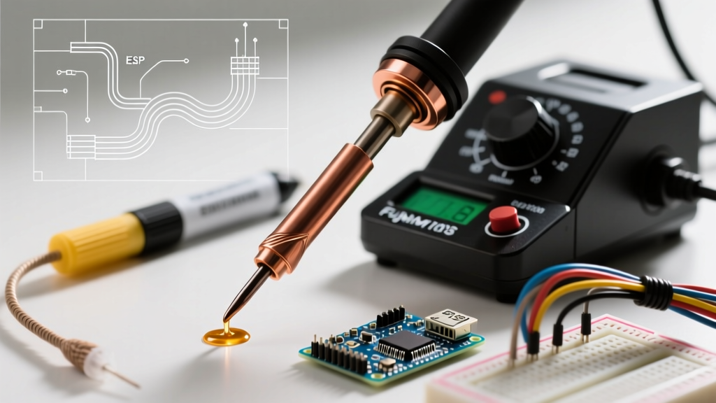

Properly tinning a soldering iron is not merely a matter of melting solder onto the tip; it is a precise metallurgical process that dictates the thermal efficiency and operational lifespan of your equipment. According to the IPC-J-STD-001 requirements for soldered electrical and electronic assemblies, a properly tinned tip ensures optimal heat transfer and prevents the formation of insulating oxide layers. Whether you are using a high-end Hakko FX-951 or a budget-friendly Pinecil, the physics of tip wetting remain constant. This setup and calibration tutorial will guide you through the exact parameters required for tinning soldering iron tips, ensuring your station is dialed in for professional-grade electronics work.
The Thermodynamics of Tip Wetting and Oxidation
Modern soldering iron tips are not solid copper. They consist of a high-conductivity copper core coated with a protective iron plating, typically 100 to 150 microns thick, followed by a chromium or nickel layer at the base to prevent solder from wicking up the shaft. The working end is bare iron, which readily wets with molten solder to form a thin intermetallic compound (IMC) layer, usually Cu6Sn5.
When bare iron is exposed to atmospheric oxygen at temperatures above 200°C, it rapidly forms iron oxide (Fe2O3). This black crust acts as a severe thermal insulator. If you attempt to solder with an oxidized tip, the thermal resistance spikes, forcing you to apply excessive pressure and dwell time, which ultimately destroys the component pads and the tip itself. Tinning creates an airtight metallic seal, sacrificing the solder to oxidation while protecting the underlying iron plating.
Station Calibration: The Prerequisite to Tinning
Before you begin the tinning process, your soldering station must be accurately calibrated. Digital readouts on stations like the Weller WE1010NA or Hakko FX-888D are often offset from the actual tip temperature due to thermal lag and sensor placement. Calibrating ensures you are not accidentally overheating the flux or underheating the alloy during the critical tinning phase.
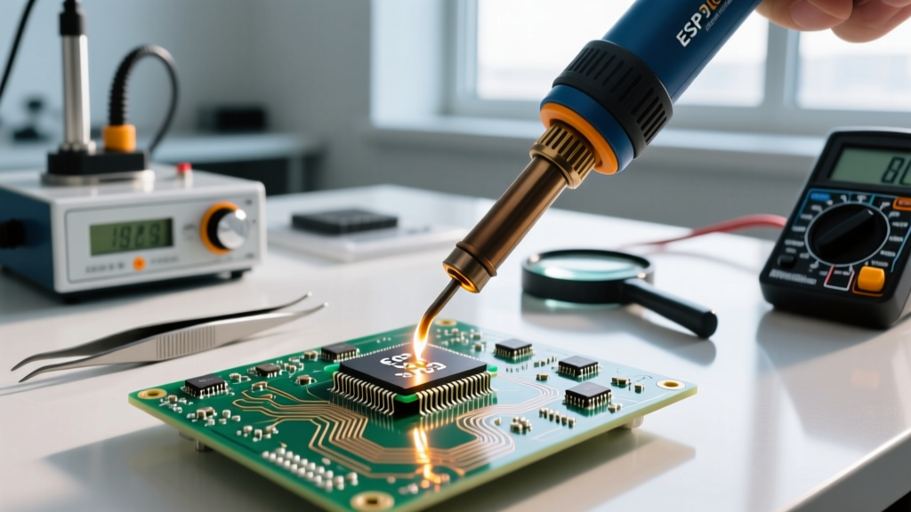
To calibrate, use a dedicated tip thermometer (such as the Hakko 191 or Weller WCB100). Embed the thermocouple sensor in a small blob of solder on the tip, allow a 60-second thermal soak, and adjust the station's internal offset potentiometer or digital menu until the displayed temperature matches the sensor reading within ±3°C.
Optimal Tinning Temperature Profiles by Alloy
The temperature you select for tinning must be high enough to activate the flux and promote rapid wetting, but low enough to prevent immediate flux burn-off and tip erosion. Refer to the matrix below for exact calibration targets:
| Solder Alloy | Composition | Melting Point | Ideal Tinning Temp | Flux Activation Window |
|---|---|---|---|---|
| SAC305 (Lead-Free) | 96.5% Sn, 3% Ag, 0.5% Cu | 217°C (423°F) | 320°C - 340°C | 150°C - 250°C |
| Sn63/Pb37 (Eutectic) | 63% Sn, 37% Pb | 183°C (361°F) | 250°C - 270°C | 120°C - 200°C |
| Sn96.5/Ag3.5 | 96.5% Sn, 3.5% Ag | 221°C (430°F) | 330°C - 350°C | 150°C - 250°C |
The 4-Step Tinning Soldering Iron Protocol
Whether you are prepping a brand-new tip out of the box or recovering a lightly oxidized one, follow this exact sequence to establish a flawless solder coat.
- Pre-Fluxing the Surface: Before the iron reaches full temperature, apply a small drop of mildly activated rosin flux (such as Kester 186 RMA) to the cold tip. As the station heats up through the 100°C–150°C range, the flux will activate, dissolving any microscopic surface oxides before they can bake onto the iron plating.
- The Capillary Melt: Once the station hits your target calibration temperature (e.g., 320°C for SAC305), immediately apply a generous amount of thick, flux-cored solder wire (0.031" or 0.8mm diameter is ideal). Do not use thin wire, as the flux will burn off before sufficient solder melts. Ensure the solder flows evenly across the entire working surface via capillary action.
- Controlled Wiping: Wipe the tip to remove excess solder and flux residue. Never use a wet cellulose sponge. The thermal shock of a 200°C delta-T causes micro-fractures in the iron plating, leading to premature pitting. Instead, use a dry brass wire sponge (e.g., Hakko 599B). Wipe at a 45-degree angle with light pressure (under 200 grams) to clean the tip without scratching the plating.
- The Shutdown Coat: Immediately after wiping, apply a fresh, thick layer of solder to the tip. This is your sacrificial shield. When you turn the station off, this outer layer will oxidize as it cools, leaving the underlying iron plating perfectly preserved for your next session.
Critical Warning: Never file, sand, or use emery cloth on a modern soldering iron tip. Abrasives will instantly strip the 150-micron iron plating, exposing the copper core. Once the copper is exposed, the tip will dissolve into the solder pool within hours, rendering it completely useless.
Troubleshooting Tinning Failure Modes
Even with meticulous setup, environmental factors and improper handling can lead to tinning failures. The NASA Electronic Parts and Packaging (NEPP) Program highlights several common degradation modes in high-reliability soldering environments. Here is how to identify and resolve them:
- Black Oxide Crust (Non-Wetting): Solder balls up and rolls off the tip. This occurs when the iron is left at operating temperature in the air for more than 3 minutes without a sacrificial solder coat. Fix: Lower the temperature to 250°C, apply a heavy dose of Kester 186 liquid flux, and aggressively feed solder wire while rubbing the tip against a brass sponge.
- Pitting and Corrosion: Visible craters or rough patches on the tip surface. This is almost always caused by thermal shock from wet sponges or using highly active, corrosive water-soluble fluxes (like Kester 331) that eat through the iron plating. Fix: The tip is permanently damaged and must be replaced. Switch to a no-clean or RMA rosin flux and a dry brass sponge.
- Solder Erosion (Scooping): The tip develops a concave hollow on the working face. This happens when using lead-free alloys at excessively high temperatures (above 380°C) or when tinning large ground planes for extended periods. The tin in the solder dissolves the iron plating. Fix: Recalibrate your station to a lower baseline temperature and use a chisel tip with higher thermal mass rather than turning up the heat on a fine conical tip.
Advanced Recovery: Chemical Tip Tinner vs. Abrasives
When standard flux and solder fail to re-wet a heavily oxidized tip, technicians often reach for chemical tip tinner, such as the MG Chemicals 8341 Tip Tinner (typically priced around $12.50 per jar). This compound is a highly active, acidic paste mixed with fine solder powder.
To use it, dip the hot, oxidized tip into the paste for exactly 2 to 3 seconds. The aggressive flux strips the heavy oxide layer, while the embedded solder powder immediately wets the newly exposed iron. Wipe it clean on a brass sponge and immediately apply standard flux-cored solder to neutralize any remaining acidic residue. While highly effective, chemical tinner should be a recovery tool of last resort, not a daily maintenance step, as the harsh chemistry will slowly degrade the iron plating over repeated uses. A well-calibrated station and strict adherence to the shutdown coat protocol will eliminate the need for chemical tinner in 95% of daily DIY and professional workflows.