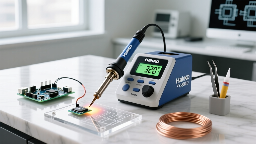

Introduction to the Hakko FX-888D Digital Station
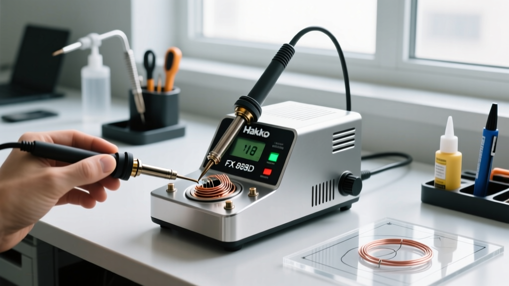
The Hakko FX-888D soldering station remains a benchmark in professional and advanced hobbyist electronics workbenches in 2026. Upgrading the legacy analog FX-888 with a digital display, push-button controls, and a compact footprint, the FX-888D delivers 70 watts of stable power through the exceptional FX-951 handpiece. Retailing between $125 and $140, it is an investment that demands proper care. While Hakko tools are renowned for their longevity, daily thermal cycling, flux corrosion, and physical wear inevitably lead to performance degradation. This comprehensive troubleshooting and maintenance guide provides actionable, expert-level diagnostics to keep your station operating within IPC J-STD-001 compliance standards.
Decoding FX-888D Error Codes: H-E and S-E
The digital display on the FX-888D is not just for temperature readouts; it is your primary diagnostic interface. When the station detects a critical failure in the handpiece circuit, it halts power to the heating element and flashes an error code. Understanding the distinction between these codes is the first step in targeted troubleshooting.
H-E (Heater Error)
An H-E code indicates an open or short circuit in the ceramic heating element. This is the most common failure mode, usually caused by a burnt-out heater coil or a severed wire inside the handpiece cord near the strain relief. Before ordering a replacement B2032 heater assembly (approximately $18), verify the failure with a digital multimeter.
S-E (Sensor Error)
An S-E code points to a failure in the thermocouple sensor circuit. The FX-951 handpiece uses an integrated heater and sensor assembly. If the station cannot read the micro-voltage changes from the thermocouple, it triggers an S-E to prevent thermal runaway. Like the H-E, this typically requires a full heater/sensor cartridge replacement.
Multimeter Diagnostics: The 5-Pin Handpiece Connector
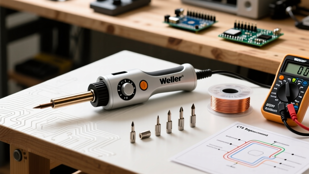
To accurately diagnose whether the fault lies in the station's internal board, the cord, or the handpiece heater, unplug the handpiece from the station. Set your multimeter to the lowest Ohms (Ω) range and probe the 5-pin connector on the handpiece cable. Compare your readings to the diagnostic matrix below.
| Probe Points | Component Tested | Expected Resistance (Ω) | Failure Indication |
|---|---|---|---|
| Pin 1 to Pin 5 | Ceramic Heater Element | 10 Ω to 15 Ω | OL (Open Loop) or 0 Ω (Short) |
| Pin 2 to Pin 3 | Thermocouple Sensor | 2 Ω to 3 Ω | OL (Open Loop) |
| Pin 4 to Tip Barrel | Earth Ground Continuity | < 1 Ω | > 1 Ω (Ground fault / ESD risk) |
Note: If your multimeter reads within the expected ranges at the cord's plug but the station still throws an H-E or S-E, the internal socket on the FX-888D mainboard may have oxidized pins or a cracked solder joint requiring internal station repair.
Step-by-Step Handpiece Teardown and Heater Replacement
If your multimeter confirms a dead heater or sensor, replacing the B2032 assembly is a straightforward process. You will need a small Phillips screwdriver and a pair of tweezers.
- Remove the Tip: While the handpiece is cold, unscrew the T18 tip sleeve and slide off the tip. Never attempt this while the station is hot.
- Unscrew the Strain Relief: Grip the rubber strain relief at the base of the handpiece and twist the knurled plastic nut counterclockwise.
- Extract the Ceramic Heater: Gently pull the heater assembly straight out of the steel barrel. Warning: The ceramic heater is extremely brittle. Bending it laterally will snap it instantly.
- Inspect the Filter: Inside the barrel, you will find a tiny ceramic wool filter (Part #B2033). If it is blackened with burnt flux, replace it. A clogged filter restricts airflow, causing the heater to overheat and fail prematurely.
- Install the New Assembly: Push the new B2032 heater into the barrel until it seats firmly. Ensure the wires are not pinched against the steel housing when reattaching the strain relief.
T18 Tip Metallurgy and Preventative Maintenance
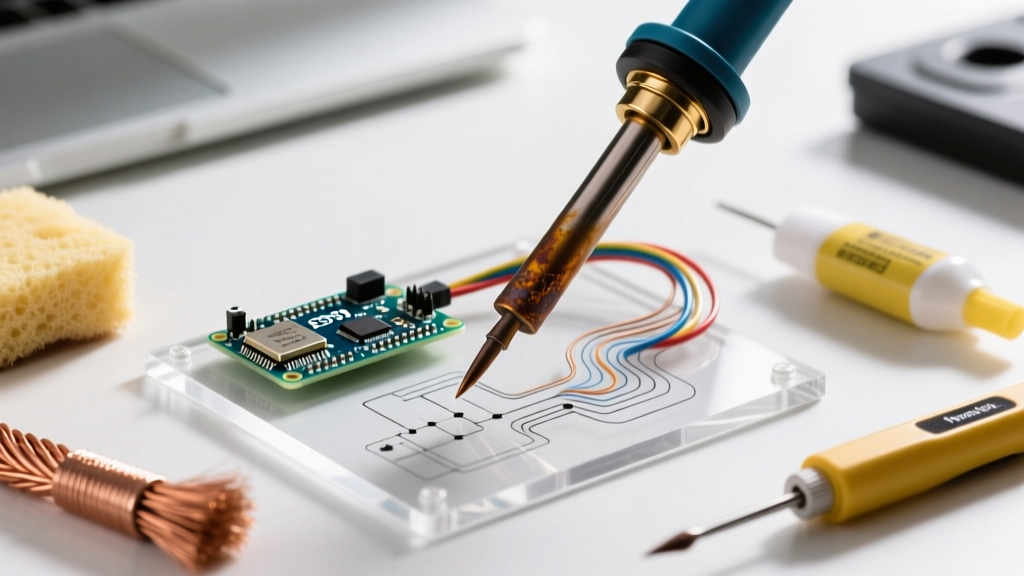
The T18 series tips utilized by the FX-888D feature a highly engineered construction: a high-conductivity copper core plated with iron to resist solder dissolution, followed by a chromium layer to prevent solder from wetting the non-working areas. Understanding this metallurgy is critical for maintenance.
Expert Warning: Never use abrasive materials, sandpaper, or files on a T18 tip. Removing the microscopic iron plating exposes the copper core, which will rapidly dissolve into the molten solder alloy, destroying the tip in a matter of hours. Always adhere to NASA's Workmanship Training standards for soldering, which explicitly forbid mechanical abrasion of iron-plated tips.
The Brass Sponge vs. Cellulose Sponge Debate
While Hakko includes a damp cellulose sponge with the FX-888D, relying on it exclusively introduces severe thermal shock. Dropping a 350°C tip into water-soaked cellulose causes rapid contraction, leading to micro-fractures in the iron plating. For daily maintenance in 2026, we strongly recommend the Hakko 599B brass wire sponge. The brass coils scrape away oxidized flux and carbon buildup without dropping the tip's temperature significantly, preserving the structural integrity of the plating and reducing thermal recovery load on the 70W heater.
Advanced Calibration: Tuning the Thermocouple Offset
Over time, the thermocouple's voltage output may drift, causing the digital display to show a temperature that differs from the actual tip temperature. To maintain compliance with strict IPC J-STD-001 soldering requirements, you should calibrate the station every 6 months using a dedicated tip thermometer like the Hakko FG-100B.
Calibration Procedure
- Step 1: Power off the FX-888D station completely.
- Step 2: Press and hold both the UP arrow button and the ENTER button simultaneously.
- Step 3: While holding both buttons, turn the power switch ON. The display will flash
CAL, indicating you have entered the offset calibration mode. - Step 4: Release the buttons and press ENTER. The station will now heat the iron to the default set point (usually 350°C).
- Step 5: Once the temperature stabilizes, measure the actual tip temperature using your FG-100B tip thermometer.
- Step 6: Use the UP and DOWN arrows to adjust the digital display to match the exact reading on your external thermometer.
- Step 7: Press ENTER to save the offset value to the EEPROM. The station will reboot and apply the new calibration curve.
Configuring Auto-Sleep and Thermal Management
Leaving the FX-888D at 400°C while not actively soldering accelerates tip oxidation exponentially. The station features a built-in auto-sleep function that drops the temperature to 200°C after a user-defined period of inactivity. To configure this:
- Press and hold the * (asterisk) button until the display flashes
SLP. - Use the UP and DOWN arrows to set the idle time (options range from 1 to 9 minutes, or 0 to disable).
- Press ENTER to confirm.
When the handpiece is placed in the holder and the sleep timer expires, the display will show a flashing temperature. Simply pick up the handpiece or press any button to instantly wake the station and trigger the 70W rapid-heat recovery.
Internal Power Supply and Fuse Diagnostics
If your FX-888D shows no signs of life—no display, no LED illumination—the issue is likely upstream of the microcontroller. First, verify your AC power cable and outlet. If power is confirmed, the internal thermal fuse or main glass fuse may have blown due to a power surge. Opening the station requires removing the four rubber feet and the underlying Phillips screws. Inside, locate the 1A 250V slow-blow glass fuse on the PCB near the AC input. Test it for continuity. If blown, replace it with an identical slow-blow (time-delay) fuse. Never replace a slow-blow fuse with a fast-acting fuse, as the initial inrush current of the station's 70W transformer will instantly blow a fast-acting fuse upon startup.
Conclusion
The Hakko FX-888D is a workhorse designed to withstand years of rigorous use, provided it is maintained correctly. By mastering multimeter diagnostics on the 5-pin connector, utilizing brass sponges to prevent thermal shock, and routinely calibrating the thermocouple offset, you ensure your soldering station delivers the precise thermal profiles required for modern, high-density PCB assemblies. Keep a spare B2032 heater and a pack of B2033 filters in your lab inventory to minimize downtime when components inevitably reach the end of their lifecycle.