
The Metallurgy Behind Tinning the Soldering Iron
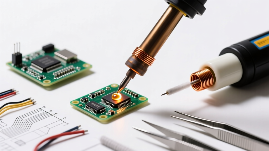
To truly master tinning the soldering iron, one must first understand the microscopic battlefield occurring at the tip’s surface. Modern soldering iron tips, such as the Hakko T18 series or Weller ET series, are not solid metal. They consist of a high-conductivity copper core electroplated with a protective iron layer, typically ranging from 100 to 250 microns thick. This iron plating prevents the molten solder from dissolving the copper core—a destructive process known as leaching.
When you apply solder to this iron plating, a metallurgical bond forms. The tin (Sn) in the solder reacts with the iron (Fe) to create an Intermetallic Compound (IMC) layer, primarily FeSn2. According to metallurgical data published by the Indium Corporation, this IMC layer is critical. If the layer is too thin (under 1 micron), the solder will de-wet and ball up. If it grows too thick (over 5 microns) due to excessive heat or prolonged exposure, the joint becomes brittle, and the tip’s thermal transfer efficiency plummets. Tinning is the deliberate act of maintaining this IMC layer at an optimal 1 to 3 microns, sealing the iron plating away from atmospheric oxygen.
The Thermodynamics of Oxidation and "Black Tip" Syndrome
When a soldering iron is left idle at high temperatures, the iron plating reacts with oxygen in the air to form iron oxide (Fe2O3). This oxidation process accelerates exponentially once the tip temperature exceeds 250°C (482°F). Iron oxide is a thermal insulator and is completely non-wettable by solder. This manifests as the dreaded "black tip" syndrome, where molten solder simply rolls off the oxidized surface.
Furthermore, flux residues from rosin-based (RMA) or water-soluble wire solder can carbonize on the tip if not cleaned regularly. This carbon buildup acts as a secondary thermal barrier. Proper tinning creates an airtight metallic seal that physically blocks oxygen from reaching the iron plating, effectively pausing the oxidation clock.
Step-by-Step Protocol: Tinning the Soldering Iron Correctly
Executing a perfect tin requires precise thermal management and timing. Follow this protocol to ensure maximum tip longevity and optimal thermal transfer.
Phase 1: Thermal Soak and Stabilization
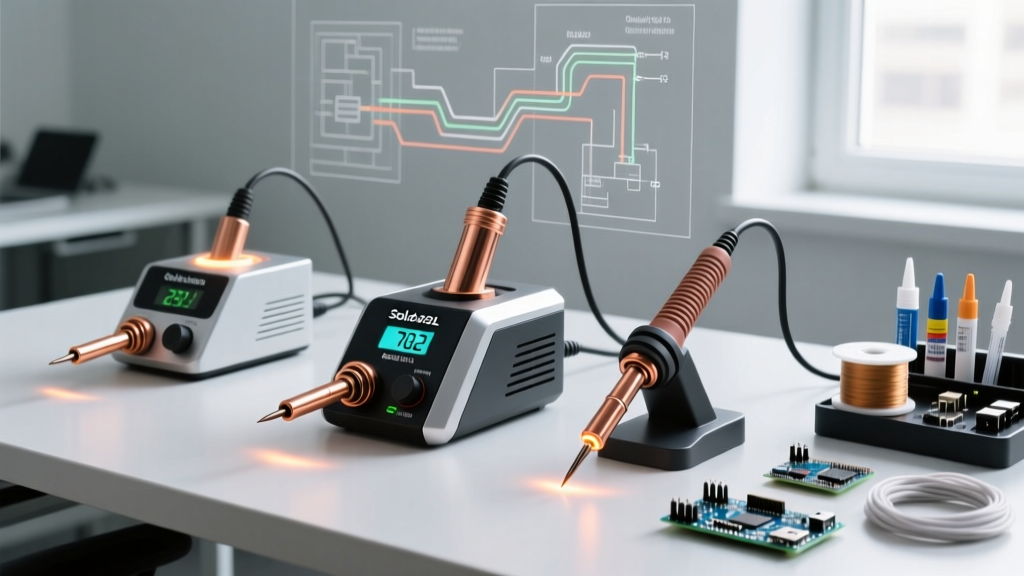
Do not apply solder the second the iron begins heating. Wait for the station’s thermal recovery indicator to confirm the setpoint has been reached. For standard Sn63/Pb37 (63/37) leaded solder, set your station to 315°C (600°F). For lead-free SAC305 (Sn96.5/Ag3.0/Cu0.5), set it to 350°C (662°F). Allow the tip to soak at this temperature for 30 seconds to ensure the internal copper core and external iron plating are in thermal equilibrium.
Phase 2: Flux Activation
Apply a generous amount of high-quality flux to the tip before introducing the solder alloy. Using a no-clean flux like Kester 245 or a standard rosin flux helps strip away any microscopic surface oxides that formed during the heat-up phase. The Kester (MacDermid Alpha) technical data sheets emphasize that flux activation prior to solder application dramatically improves initial wetting speed.
Phase 3: Alloy Deposition and Capping
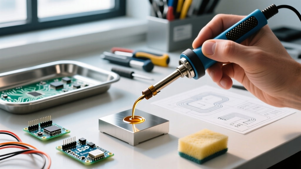
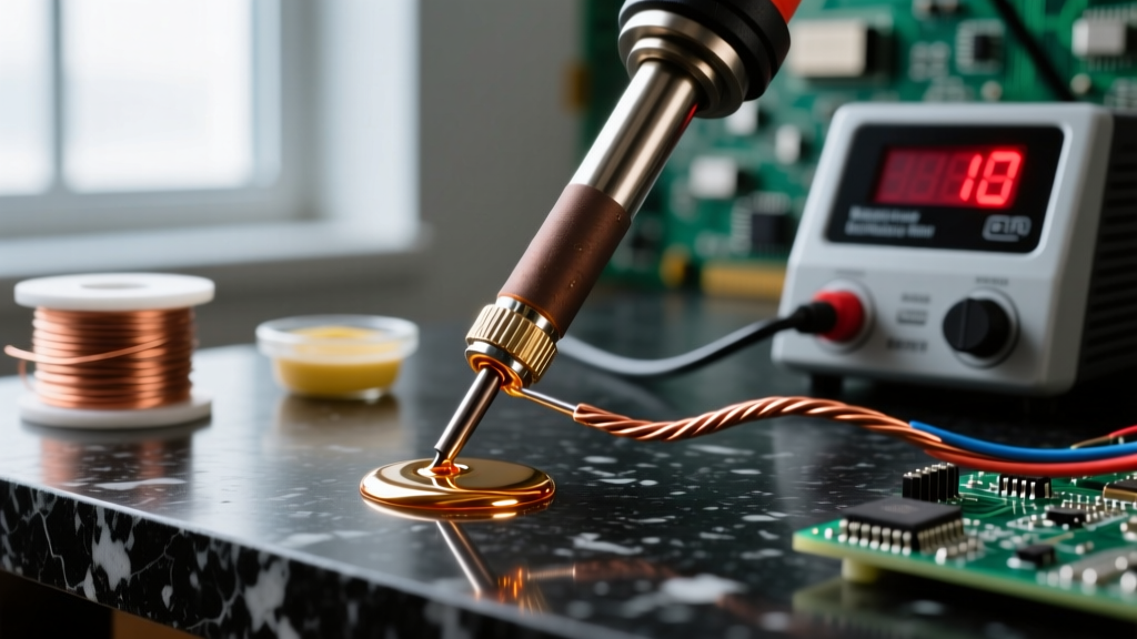
Feed your solder wire directly into the junction of the tip and the flux. Melt a generous blob—enough to coat the entire working surface and slightly spill over the edges. This is known as "capping." Never wipe the tip clean before turning off the station. The solidified solder cap will act as a sacrificial anode, oxidizing in place of the iron plating while the tool cools down and sits idle.
Alloy Selection Matrix for Tip Tinning
Not all solder alloys are created equal when it comes to tip maintenance. The choice of alloy used strictly for tinning can drastically alter the lifespan of your iron plating. Below is a comparison matrix of common alloys used for tinning.
| Alloy Composition | Melting Point | Wetting Speed | Tip Wear Rate | Best Use Case for Tinning |
|---|---|---|---|---|
| Sn63/Pb37 (Leaded Eutectic) | 183°C (361°F) | Very Fast | Low | Daily tinning, prototyping, general DIY |
| SAC305 (Lead-Free) | 217°C (423°F) | Moderate | High | Mandatory for strict RoHS production environments |
| Sn99.3/Cu0.7 (Lead-Free) | 227°C (441°F) | Slow | Very High | Plumbing and heavy-gauge wire (avoid for micro-tips) |
| Sn60/Pb40 (Leaded Non-Eutectic) | 183-190°C | Fast | Low | Cost-effective bulk tinning for hobbyists |
Expert Insight: If your workflow requires lead-free soldering (SAC305) for the actual PCB joints, it is highly recommended to maintain a separate spool of cheap Sn63/Pb37 solder exclusively for tinning the iron before powering it down. The leaded alloy wets faster, requires lower idle temperatures, and causes significantly less iron dissolution during the cooling phase. Just ensure you clean the leaded solder off with brass wool before making your lead-free production joints to avoid cross-contamination.
Mechanical Cleaning: Brass Wool vs. Cellulose Sponges
The method you use to clean the tip during a soldering session directly impacts the integrity of the tin layer and the underlying iron plating.
- Damp Cellulose Sponges: Wiping a 350°C tip on a wet sponge causes an instantaneous temperature drop of over 100°C. This severe thermal shock induces micro-fractures in the iron plating. Over time, these fractures allow molten solder to penetrate the iron layer and attack the copper core, leading to catastrophic tip failure (pitting and hollowing).
- Brass Wool (e.g., Hakko 599B): Brass is softer than the iron plating but harder than the solder and carbonized flux. Scraping the tip through dry brass shavings removes oxides and excess solder without dropping the tip temperature. This maintains the thermal mass required for the next solder joint and preserves the structural integrity of the plating.
Industry Standard Note: The IPC (Association Connecting Electronics Industries) workmanship standards heavily emphasize maintaining stable thermal profiles during soldering. Excessive thermal cycling via wet sponges violates best practices for high-reliability electronics assembly, as it degrades the tip’s ability to deliver consistent heat to the pad.
Emergency Re-Tinning: Salvaging Oxidized Tips
If a tip has been left on idle for hours and is completely black and de-wetted, do not immediately throw it away or resort to sandpaper. Sanding or filing will strip the 150-micron iron plating in seconds, permanently ruining the tip. Instead, use a chemical re-tinning compound.
The Re-Tinning Procedure
- Lower the Temperature: Drop your station temperature to 250°C (482°F). High heat will instantly burn the aggressive flux inside the tip tinner.
- Apply Tip Tinner: Dip the oxidized tip into a commercial tip tinner (such as MG Chemicals 4900P or Kester Tip Tinner). These compounds contain a highly active, mildly abrasive acid flux mixed with fine tin powder.
- Agitate and Melt: Gently swirl the tip in the compound for 3 to 5 seconds. The acid will strip the iron oxide, and the tin powder will immediately wet the exposed iron.
- Wipe and Re-Cap: Wipe the tip vigorously in your brass wool to remove the acidic residue, then immediately apply your standard electronics solder to create a fresh, protective cap.
Common Mistakes and Edge Cases to Avoid
Even experienced technicians fall into bad habits that accelerate tip degradation. Avoid these critical errors:
- Using Plumbing Flux on Electronics Tips: Never use zinc chloride or highly corrosive plumbing paste fluxes to clean a soldering iron tip. These acids will eat through the iron plating and ruin the internal heating element if they wick up the shaft.
- Tinning Only the Very Point: Oxidation creeps up the sides of the tip. If you only tin the extreme apex, the sides will oxidize, reducing the overall thermal mass and causing the heat sensor inside the ceramic heater to misread the tip’s actual temperature.
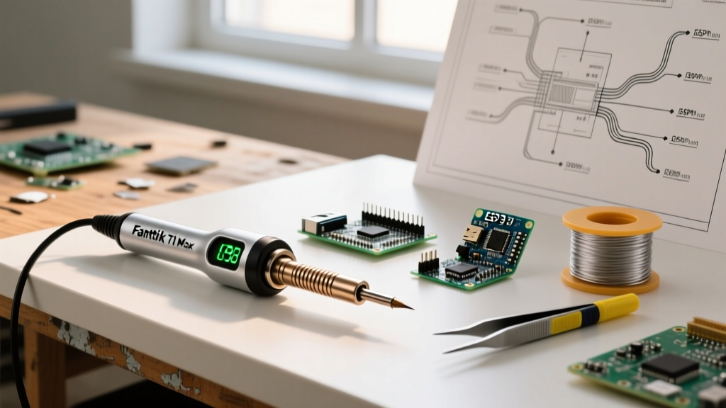
- Leaving the Iron at Maximum Heat: Running a Hakko FX-888D or Weller WE1010NA at 400°C+ when not actively soldering heavy ground planes will burn the flux out of the solder cap in minutes, leaving the iron exposed to rapid oxidation. Use your station’s sleep mode or manually turn it down to 200°C during idle periods.
Final Thoughts on Tip Longevity
Tinning the soldering iron is not merely a preparatory step; it is an ongoing metallurgical maintenance protocol. By understanding the interplay between intermetallic compounds, thermal shock, and alloy chemistry, you can extend the life of a $10 replacement tip from a few weeks to several years. Always cap your tips before powering down, rely on brass wool over wet sponges, and respect the thermal limits of your iron plating.